Suspension Adjustments
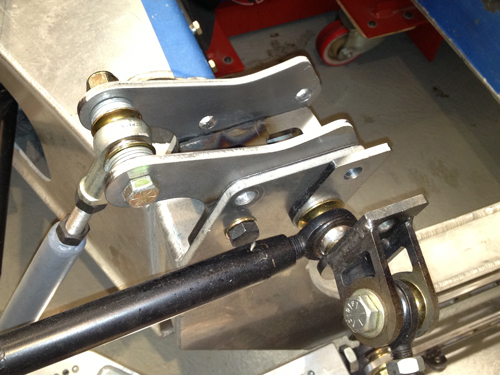
I have had the car on the road and done some great mileage. I have noticed some noises on the front end. I finally tracked the noise (a sort of deep sounding squeak and sometimes a slight knock) to the lower heims. On the top ones when the bolt is tightened the mounting points flex a little and tighten up. On the lower billet ones there is no give so exactly the right amount of spacers are required. Many use washers but they are all the right thickness so its very hard to adjust the exact castor and get everything nipped up.
So I have had a set of stainless steel shims of differing thickness made up so that I can get this right.
![]()
This allows perfect adjustment of the suspension with no play.
![]()
Guess what, now no noise!
![]()
I'm very happy. Also took the car to a show the other day. I was really happy talking to people about the car, especially kids they think its great. Seeing there face when you let them jump in is great.
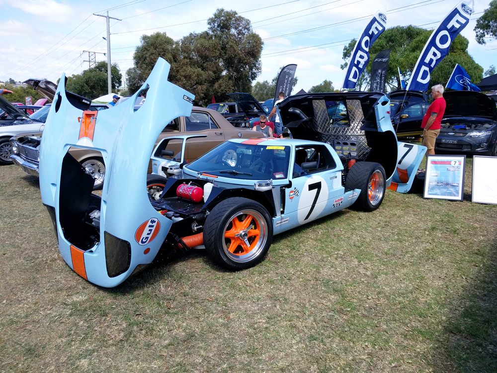
It was a great car day, 1200 cars on show and mine won best sportscar so I was very happy. Thankfully Ford does not make many sportscars!
Update : 28th February 2016
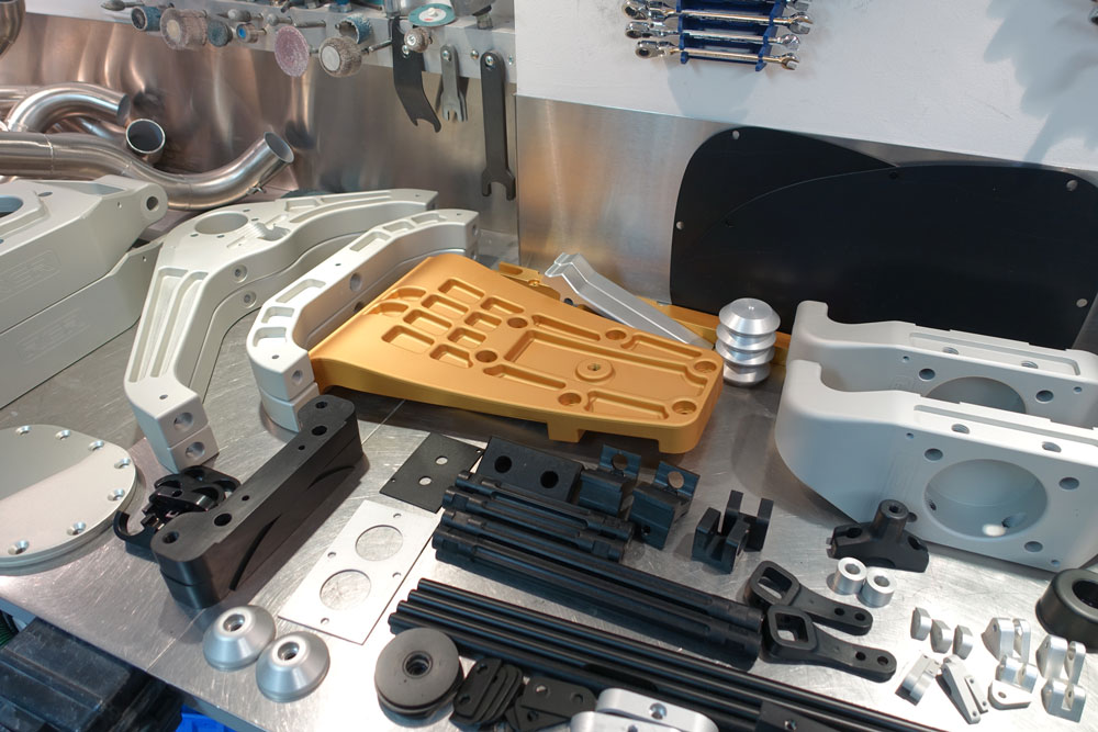
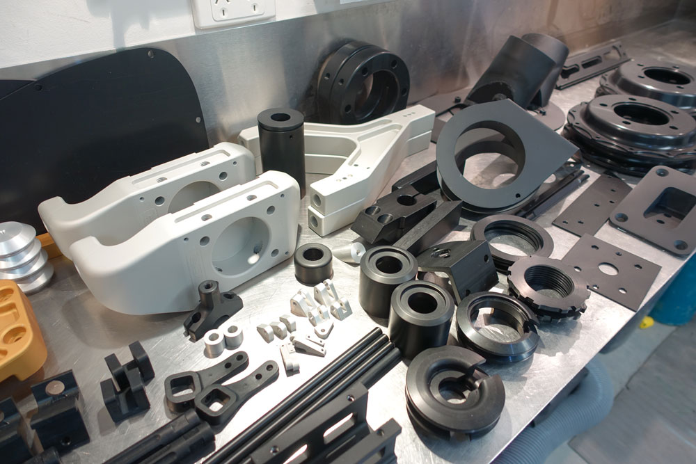
Anodised Parts
Had the first lot of parts anodised. Wow they come out good. Costs a bit here in Australia to do this but it looks cool.
Also went to SEMA this year for the first time for fun. WOW what a show, it was great.
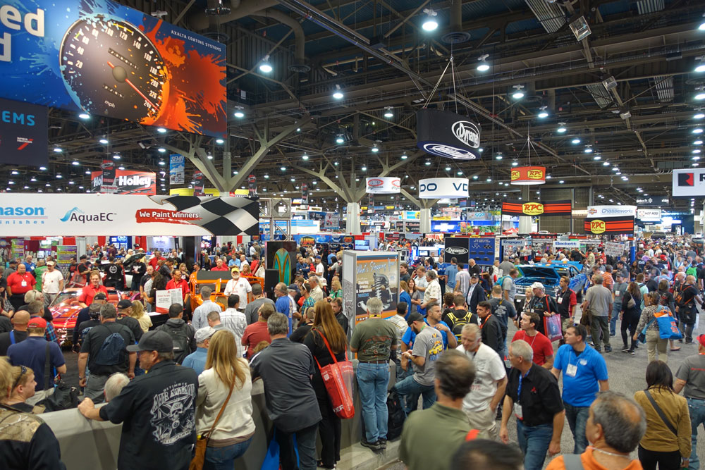
Saw lots of stuff to buy, just need more cars to use it on!.
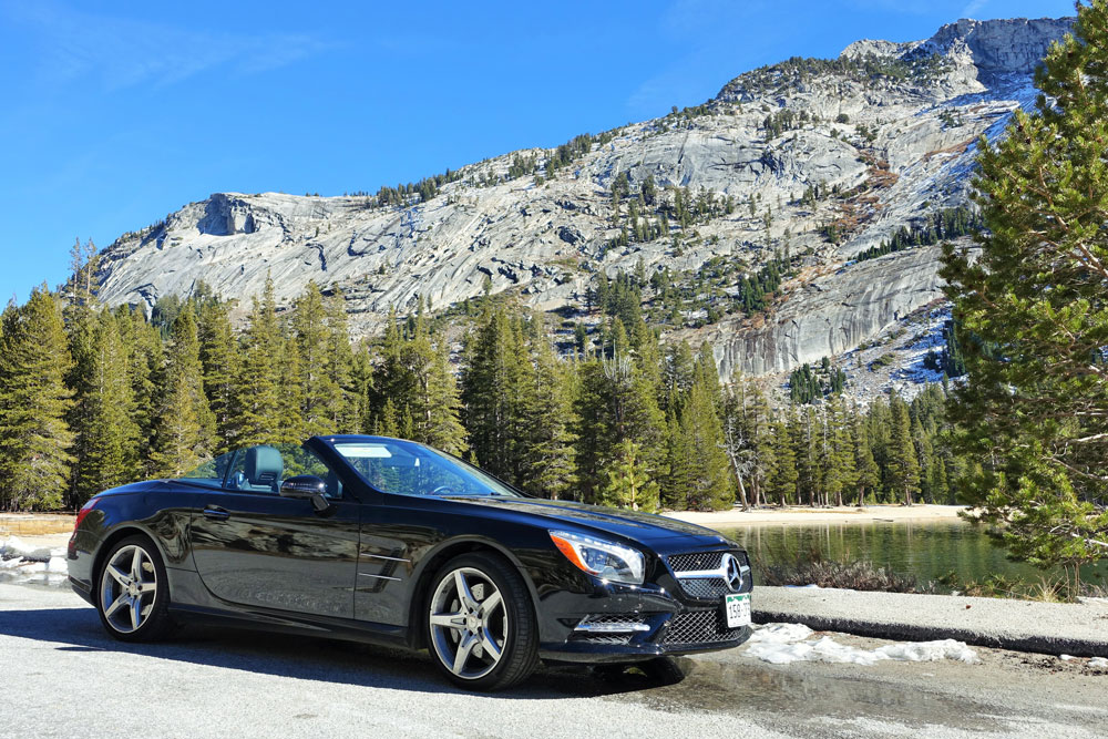
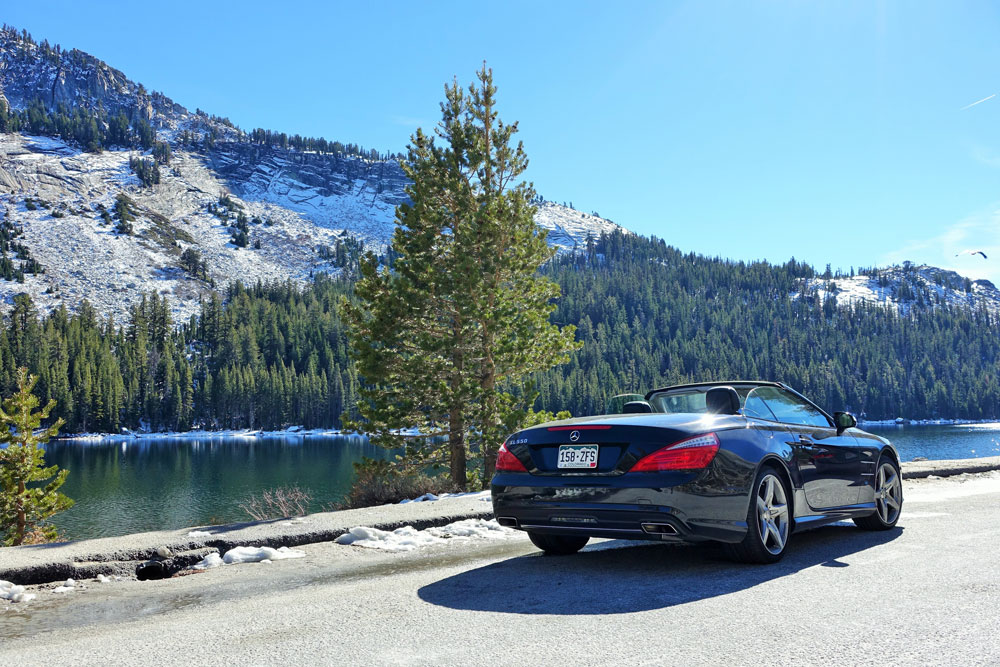
Also had a good driving holiday for 1.5 weeks with a few Aussie mates as well. Could not look at all those cool cars at SEMA and spend 1.5 weeks in the USA in a crappy rental. I got hold of a 2014 Mercedes SL550 and went from Las Vegas, Death Valley (Vmax), Mammoth, Yosemite, San Francisco, Big sur to LA and back to Vegas. Approximately 1,700 miles in the best twin turbo V8 Mercedes I have driven. Great car.
Anyhow back in Australia and need to finish the GT40. I somehow think the GT40 may not have the driver comfort that the Mercedes had!
Update : 19 November, 2014
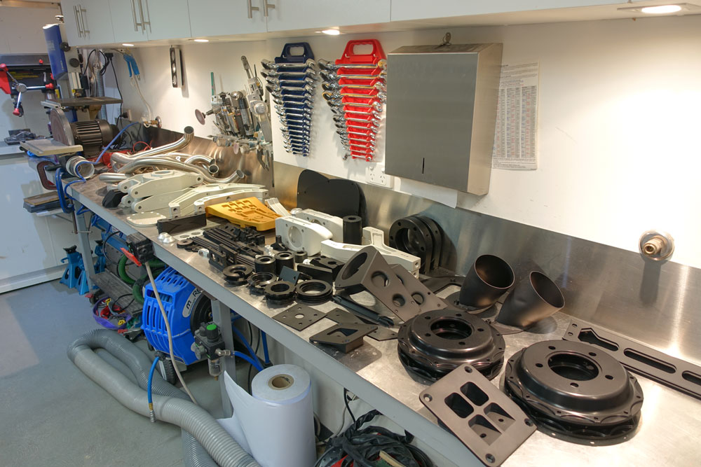
Preparing for Final Assembly
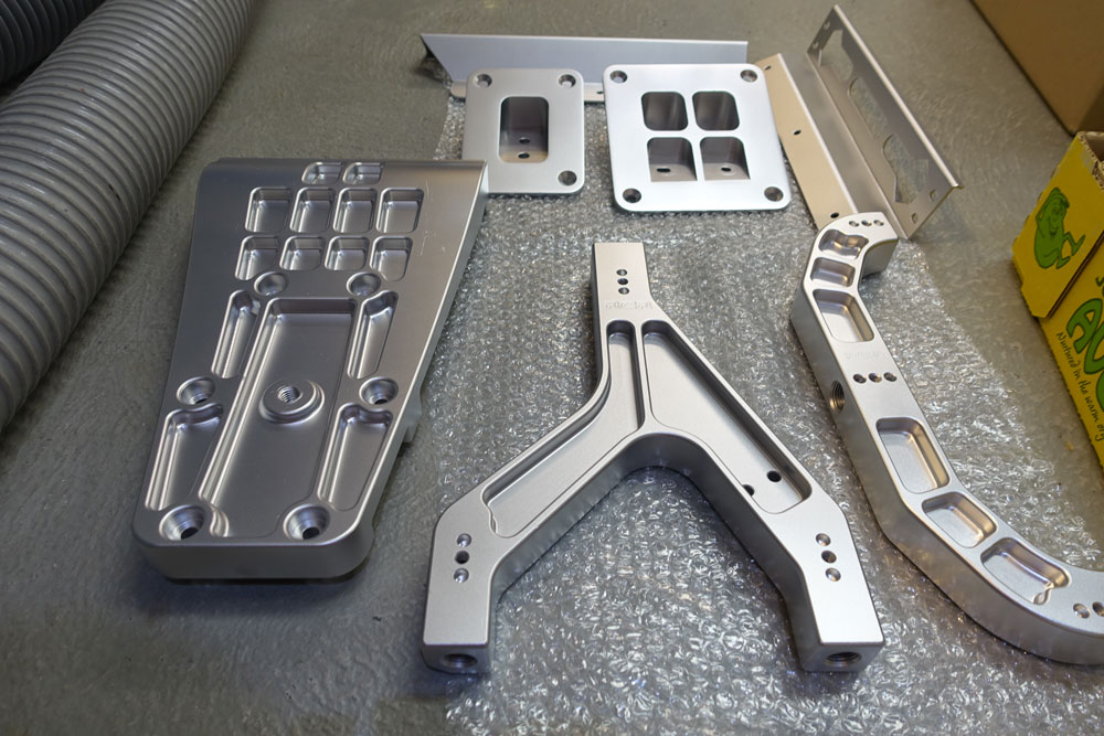
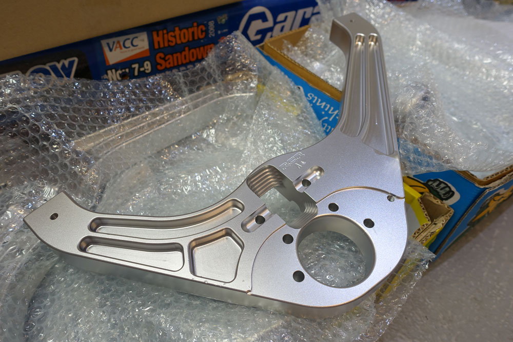
I have tried getting parts wet blasted before anodising. Wow the parts do look great. These shots are before anodising of just a few of them. Basically doing all alloy parts on the car.
Have parts out at platers, anodisers and powdercoaters as I'm leaving Australia for SEMA in Las Vegas this weekend. Never been and just wanted to go to check it out. It out to be great. Possibly see Fran there from RCR as well.
Update : 30 October, 2014
Sway Bars (Anti-roll Bars)
I really wanted to fit adjustable blade type sway bars to the GT40. Problem as always was space. I purchased the blades, bars and fixed arms from www.genesisparts.com. Pillow blocks for the bars were sourced elsewhere and are alloy with self centering bushes fitted in them, very nice units.
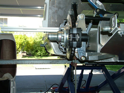
REAR
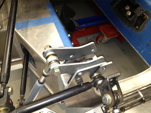
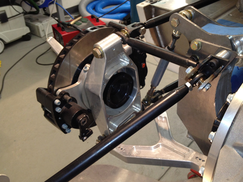
When I made the transaxle mount I left clearance between the mount and the transaxle for a bar. The modifications to the shock uprights also accommodate the sway bar bearing mounts.
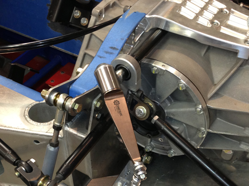
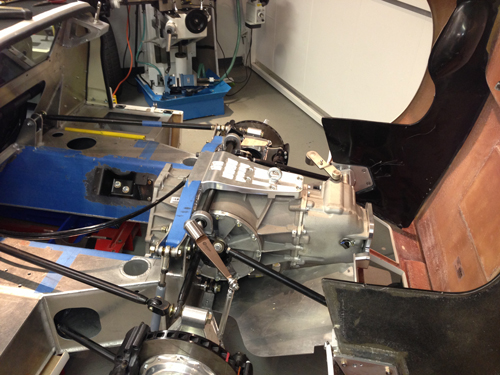
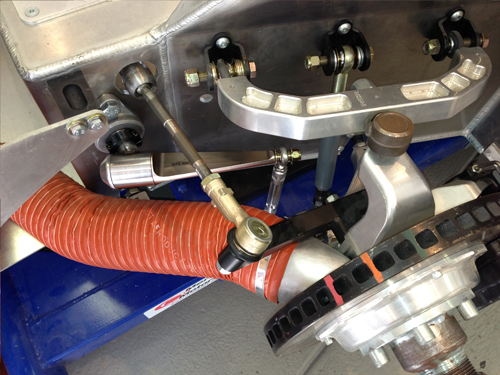
The sway bars are hollow 25mm diameter. At the end of the "blade" arm above are bearings in the supporting tube that allow it to rotate and adjust the sway bar. These are pretty common units in race applications. I used a spline on the end where the bar connects to the rigid arm so the removal of the assembly is easy. The rigid arm was milled and bolted to bend it rather than heating it up etc. The end result is very strong and exact.
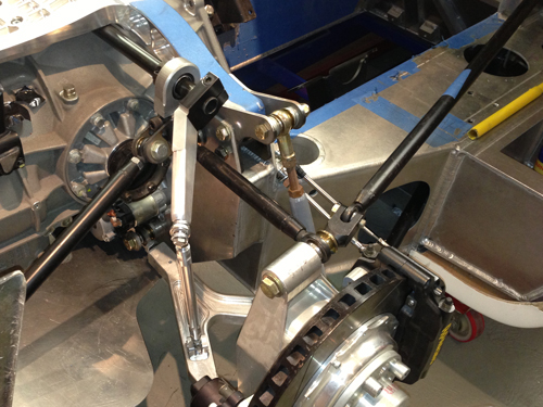
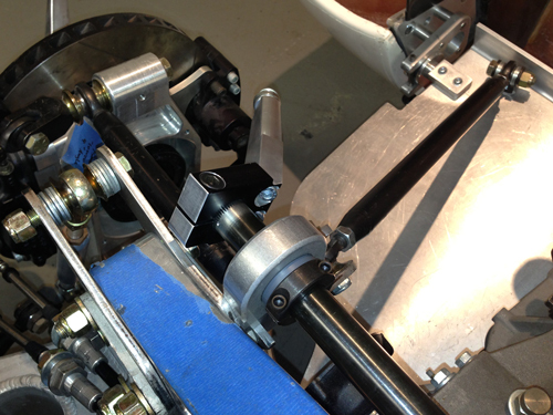
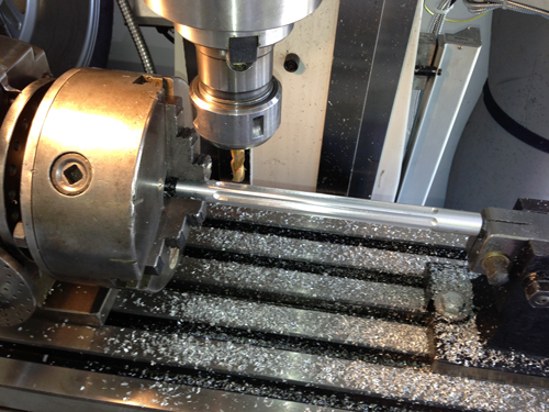
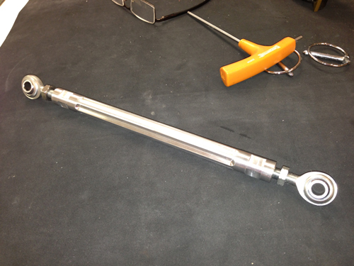
Drop links were turned up on the lathe and groved in the mill.
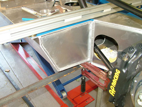
FRONT
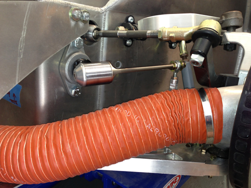
The front bar was routed through the chassis to keep the space ahead of the footbox clear. The self centering bearings ensured the bar does not bind due to it being impossible to get both sides of the chassis parallel. Missing the brake cooling duct in all suspension & steering lock combinations was tough.
Update : 5th January, 2013
Suspension Mount Hardware
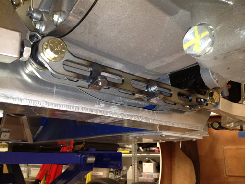
I also made some new parts for various parts of the metal work to strengthen up the upper shock & cross member mounts mounts and support the single shear lower suspension bolt as well as a few other mods. Most of the modifications are due to the large transaxle and I intend to give the car a hard time when it runs.
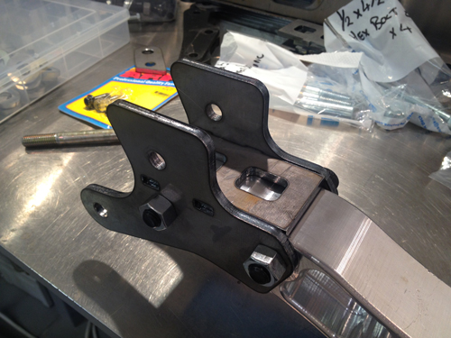
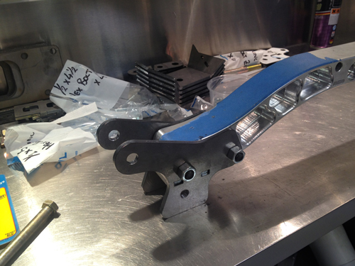
Additional bolt to the chassis allows the aluminium cross member to be removed without the suspension shock tower from collapsing which will make engine removal simpler in the future.
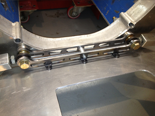
The brace below supports the lower suspension bolts that are in single shear. It also allows the removal of the bottom cover plate without removing the lower suspension arms (standard configuration).
Update : 4th January, 2013
Steering Rack Spacer
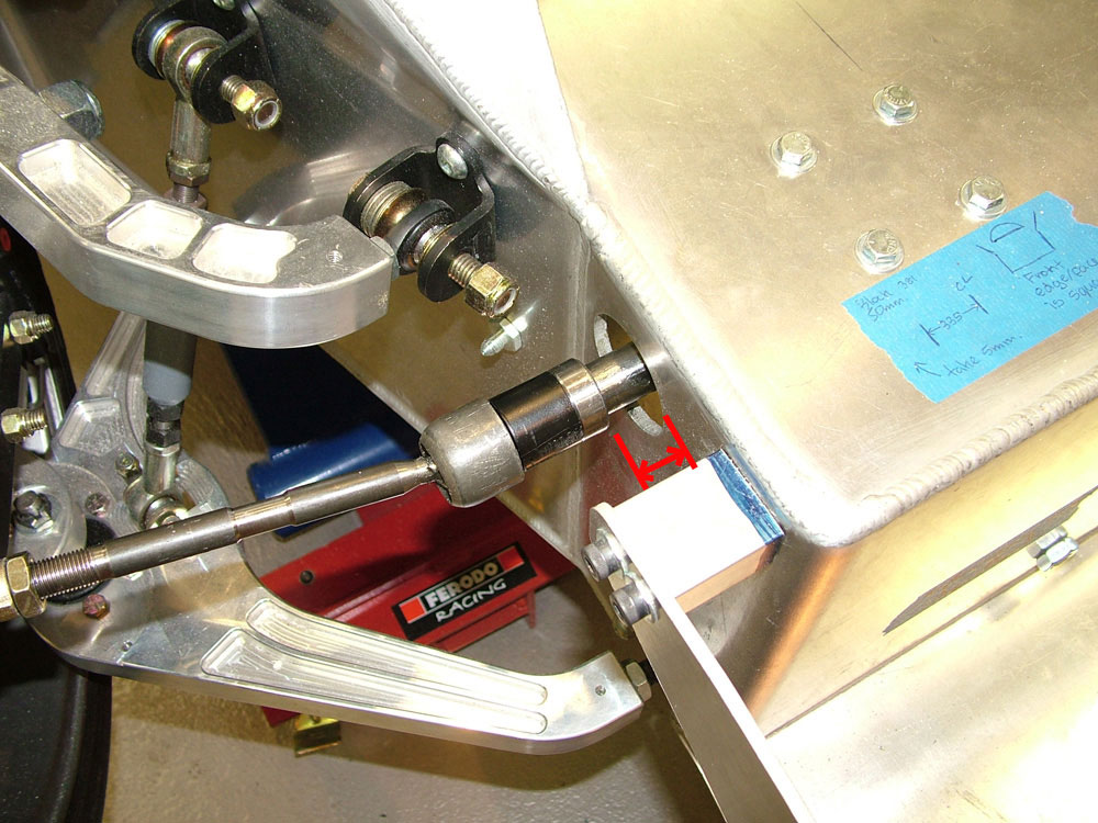
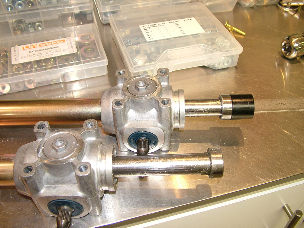
A spacer arrived from RCR that when fitted to the RHS of the rack ensures the LH and RH lock is the same. Its not a lock limiter but a rack extender. It basically accounts for the non centre position of the rack in the chassis. The rack is positioned over to the LHS of the chassis by half the thickness of the black spacer provided.
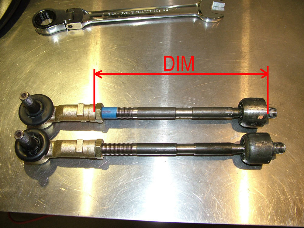
I was able to adjust the steering arms to a length of 185.5mm (RHS) and 184.5mm (LHS) with zero toe in/out with the additional spacer fitted. Having the steering arms as close to the same length as possible is very important.
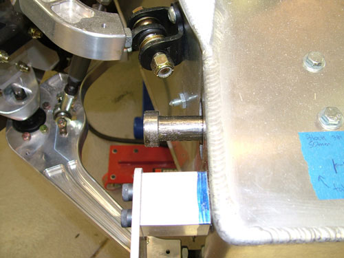
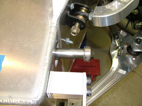
The images below show the rack fitted with the black spacer on the RHS of the rack. The distance from the RHS of the chassis to the back of the cylinder fixed to the rack is 9mm in the straight ahead position. This also provides the same lock LHS to RHS.
Update : 24th August, 2009
My Steering Lock Problem
Today I again had a look into my steering lock problem. I basically have more lock to the left compared to the right. I have 1,130 degrees of wheel rotation lock to lock (that's 3 full turns plus 50 degrees). What I have noticed is that the steering rack when turned full to the right has 50mm of the rack protruding from the chassis and when I turn to the left I have 70mm of rack protruding from the chassis. It should be even in both directions!
The total travel of the rack is 130mm lock to lock. Originally RCR felt a lock limiter was missing on one side and sent me one but they are both present so unfortunately that is not the fix.
Anyone on the GT40's forum have any ideas as RCR would not have bolted the rack too far to the left by 10mm as this would be a very critical fixing operation. Any measurements from another RCR would be great.
Update : 14th April, 2009
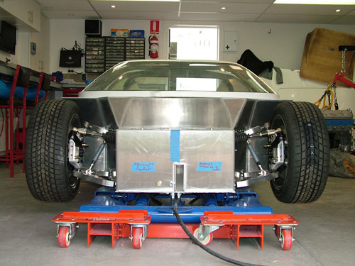
Building Ramps and Raising the suspension Height
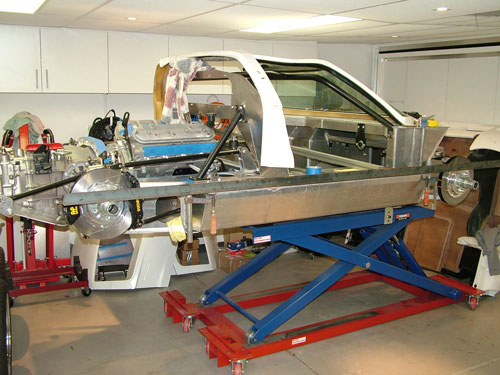
After comments that the car was too low I have decided to raise it. To get an actual check I decided to get it off the lift. The easiest way to do this was to make some ramps. They will be used when the car is finished to park the car over the lift as I have nowhere to store it. It may make it easier for me to get out of in my old age as well!
With that done I measured the previously set height. It was way too low. After a bit of adjusting I settled at below:
FRONT
Ground Clearance: 115mm (4.5") (70mm to L) , Camber: LH&RH = -1.8º, Castor: LH 6.1º & RH = 6.2º, LH&RH Toe-Out = ~ 1.5mm, Lower Arm Angle LH 3.5º & RH 3.3º
REAR
Ground Clearance: 130mm (5.1") (85mm to L) , Camber: LH&RH = -1.0º, Castor: LH&RH = 6.0º, LH&RH Toe-In = ~ 1.5mm, Lower Arm Angle LH 5º & RH 6º
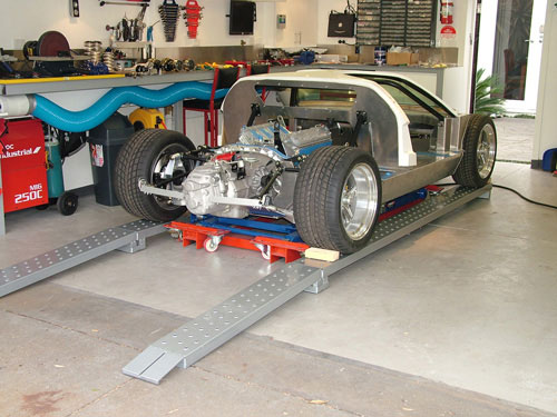
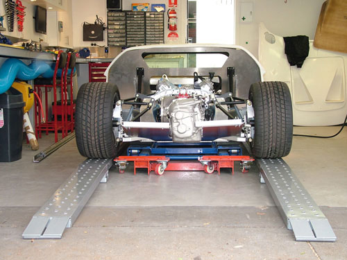
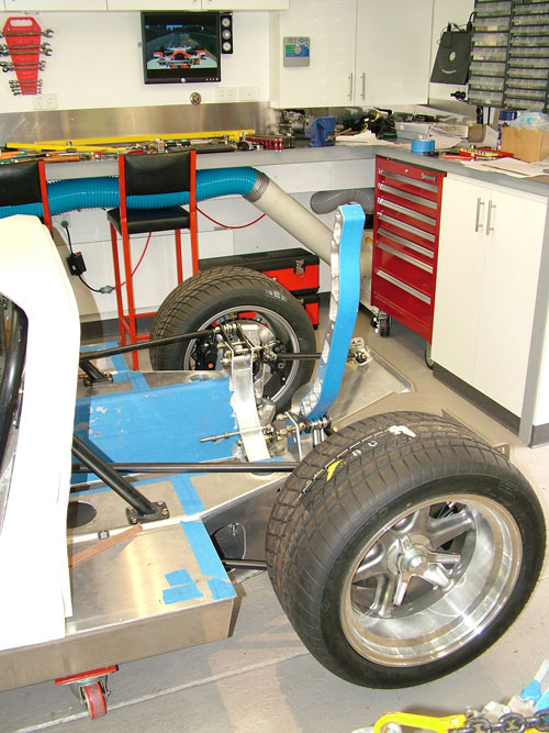
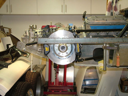
Castor is a little high and a few other issues but it should be close enough for the body fitment. Basically the car now looks like below:
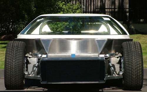
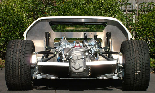
After these photos I dropped the left side of the radiator and front alloy structure to make it level.
Next job is to brace the rear panel temporarily where it was cut in half to clear the gearbox. This will permit the rear clip to be mounted.
Update : 04th November, 2008
Suspension Setup
I have chosen to setup the front ride height as 108mm (4.25") and the rear 127mm (5"). Too low anyone?
Front and rear castor was set to 6 degrees, camber rear 1 degree and is at 0 for the moment (will be set to 1.9 later). Front and rear toe in is about 1.5mm. I will set all these accurately during a professional alignment later as it will all be coming apart for painting etc. anyway.
After a lot of work the suspension was set. A lot of fiddling, I hope I do not have to start from zero again as now that I'm very close small changes are easy to make. One thing was the wheelbase, I believe the original had 2403mm (94.6"). In order for the front wheels to clear the chassis when turning and with the rear radius links close to as short as they go I could only get as low as 2408mm (94.8"). I hope this does not cause body fitting issues?
Some issues that hopefully are not problems:
1) Front lower arms look quite "angled up", I believe they should only be 3-4 degrees. This maybe for cars with lower profile wheels, not sure.
2) I had to move the upper ball joint locking nut between the arm and the joint to dial out excessive positive camber. I think I have seen others do this as well.
3 Rear radius links for the +2 kit are quite long, I really have no adjustment to make them any shorter without shaving them a little.
All in all a good day adjusting all the suspension and watching the Australian Indycar race! Next step is to source some anti-roll bars and assemble those.
Update : 26th October, 2008
Suspension Setup - Datum Bars
I have begun to attempt to setup my suspension as close as I can to enable the fitting of the body and flares. I have however a few questions that I will need to post on the GT40s forum.
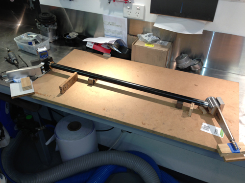
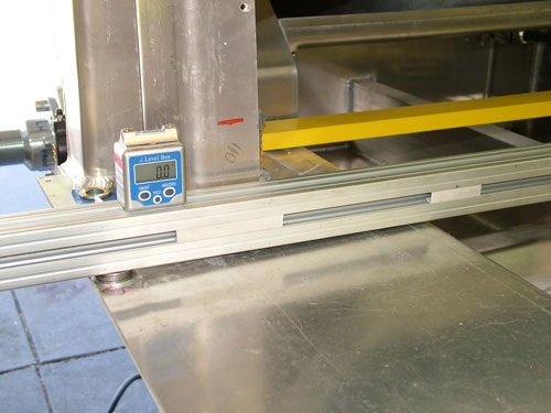
I wanted to understand any misalignments in the chassis before I started setting up the whole car so I decided to setup two very straight steel angle bars on either side of the car. I want them exactly parallel, level and distanced evenly from hard points measured on the chassis. Determining the points to base the bar positions from became tricky.
ALIGNING THE BARS TO CREATE A VEHICLE CENTRELINE
To align the bars along the sides of the car I was able to measure from the top of each fuel tank side pod at the front and the rear. Measuring out 16mm at the rear and 20mm at the front gave me two parallel bars spaced at 1680mm. The two tanks have a taper to the front of 4mm per side. Not the end of the world, just worth noting.
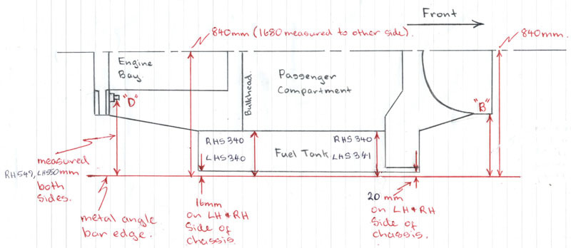
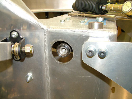
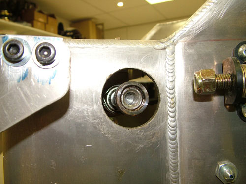
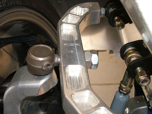
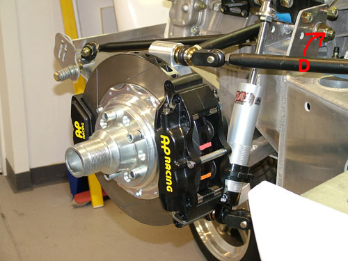
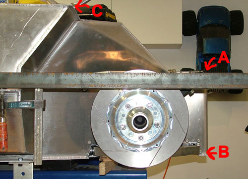
The position of the rear of the steel angle was also checked to the upper heim joint bolt marked "D" below. I chose this point as it was a critical and accessible main mount position that should be correct on both sides of the chassis. This suspension point lined up very well left (550mm) to right (549mm). Dimensions were also taken from the inside of the tanks, as above a good result here. This reinforces the position of the steel angles with the center line of the chassis. The center line lines up with the RH inside edge of the alloy tunnel tube, pretty good really.
Checking that the angles were perpendicular to the rear cross member resulted in a good pass result also. The front face of the chassis (face between A & B) is also perpendicular (within a few mm) to the steel angles. Basically the front face and rear "horseshoe" are parallel which is great.
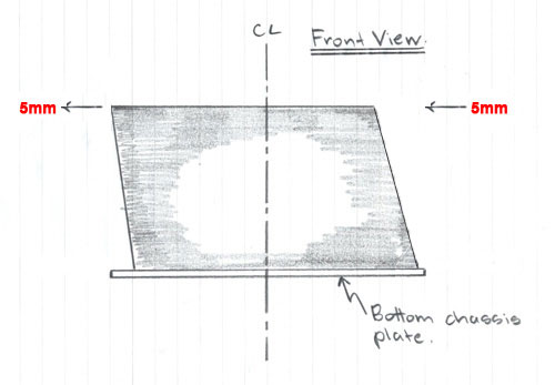
However the front alloy chassis box at "A" (where your feet go) is "parallelogramed" by 5 mm to the RHS of the vehicle (looking from behind it). This did have a slight affect on the suspension settings. I was wondering why the two metal angles were originally skewed to the RHS of the car, it was caused by taking measurements from the front top edge of the chassis at "A". The image below shows pictorially (exaggerated) what I mean. The bottom chassis plate was aligned perfectly.
ALIGNING THE BARS IN THE VERTICAL PLANE
In order to set the bars up vertically a level bar was placed on top of the tanks through the passenger compartment and in the engine bay (with the engine removed). This did show that all surfaces were level with one point worth noting. The top of the LHS tank drops by 5mm at its extreme edge.
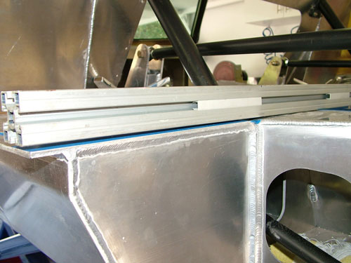
This occurs only on the LHS along its full length. 5mm spacers are placed under the LHS steel angle and I now also have a vertically level plane. This top plane based on the top of the tanks was compared to the bottom chassis plate. At the rear the LHS of the chassis plate sits 2mm lower than the right, a pretty good result. Measurements at the front show it to be level.
With the bars held firmly some checks were made on some chassis features with the following results:
1) Both tanks are 1565mm in length
2) Base of the RH A-pillar (where the door hinge attaches) is 7mm further forward than the LH one.
3) RH top radius arm mount (near the fire wall) is 3mm further forward than the left.
4) Rear edge of the top of the tanks is the datum for me to set axle distances etc.
Overall the chassis has a few dimensional "characteristics". With two parallel bars aligned to key chassis features I can begin to setup the suspension.
Update : 25th October, 2008
Referenced Suspension Setup
This page is dedicated to what will possibly be an ongoing issue with suspension. With roll bar settings, shock settings and the adjustability of the suspension geometry it will never end! Some of the info here will be based on the recommendations from others (thanks). One initial reference has been a car built by Dean Lampe. His settings are:
Dean Lampe Setup
Ride height - Front 3.87" (98mm), Rear 4.5" (114mm)
Lower A Arm angles - Front A arm angle 3.5 deg, Rear A arm angle unknown??. Assumed 0 deg.
Springs - Front 550 lbs Rear 375 lbs (wheel rate around 280 front and rear)
Ackerman 1deg toe out in 10 degs of turn
Toe in Front -1/16 (out) Rear 3/64
Camber - Front negative 1.9 degrees, Rear negative 1 degree
Caster - Front 5.8 degrees, Rear 5.6 degrees
bump steer left front bounce and droop
inch change
1 = 0.005
.75 = 0.002
.5 = 0.008
.25 = 0.002
0 = 0.000
-.25 = -.017
-.5 = -0.034
-.75 = -0.55
-1 = -0.07
bump steer right front
inch change
1 = -0.012
.75 = 0.001
.5 = 0.003
.25 = 0.005
0 = 0.000
-.25= -0.007
-.5 = -0.02
-.75 = -0.41
-1 = -0.052
Weights:
Front left 650 lbs Front Right 589 lbs
Rear left 763 lbs Rear Right 715 lbs
Front weight distribution 45.6%
Left weight distribution 52%
Total weight 2717lbs
This may be a good start. For basic setup of the suspension the methods shown here by EGLITOM are great help.
Also another link here from Randy (Big Foot).
Update : 5th July, 2008