
Dash
Work to position the switches on the dash has gone well. I really did not want to scratch the anodised alloy plates that I made to hold the switches. In the end it all worked out well. Now they are all ready to be wired up!
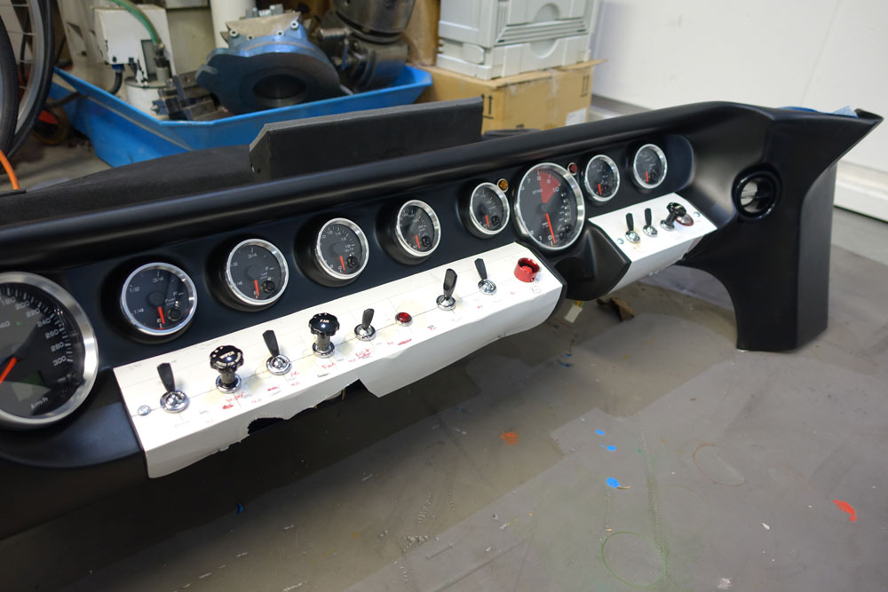
Making a paper pattern to position the switches helkped heaps.
All came out OK in the end.
Update : 31 January, 2015
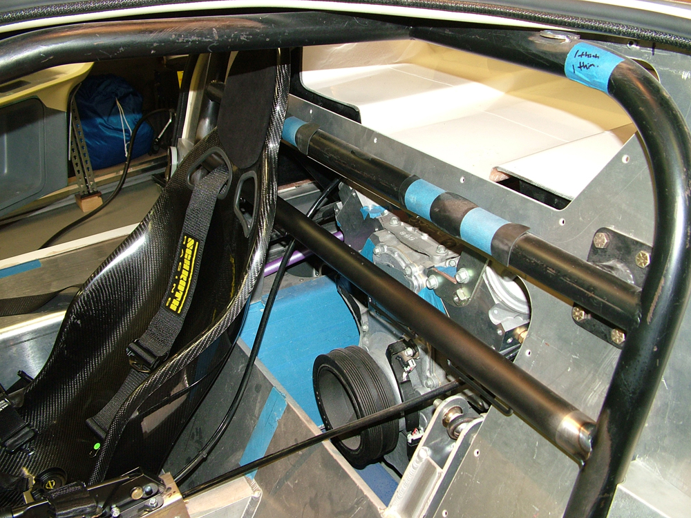
Roll Cage
I'm pretty tall and did not want my head to hit the middle cage bars so they were modified as shown.
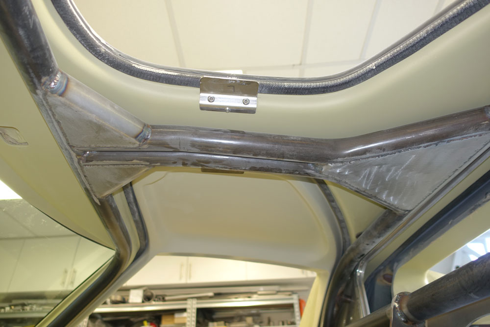
Job was done by Roaring Forties and I am very happy with the result.
Update : 15 October, 2014
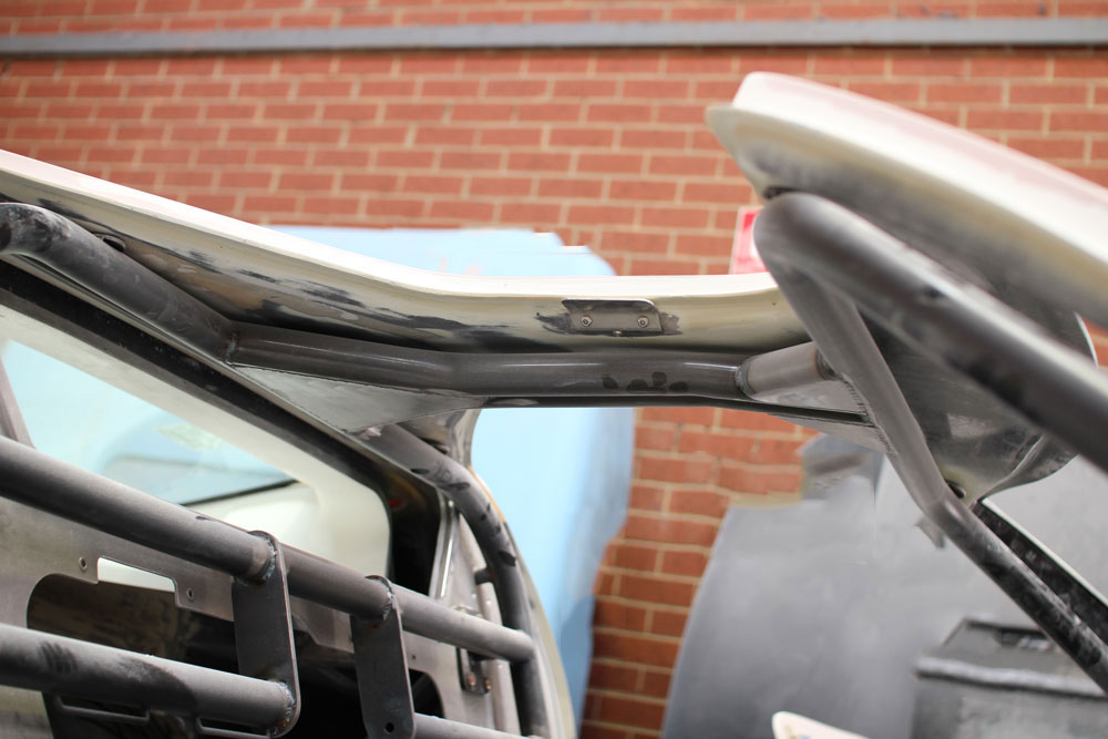
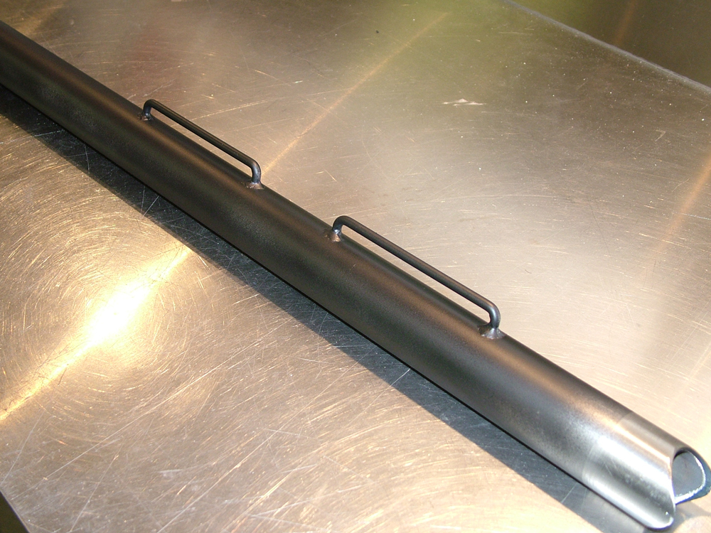
Door Closing Plates
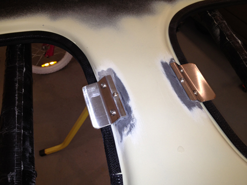
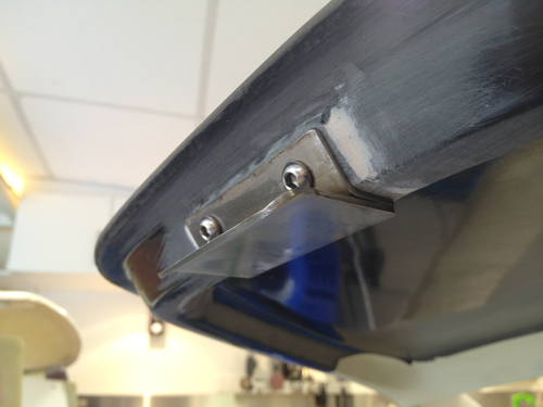
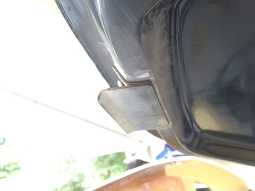
I did not want to fit door eyebrows to keep the doors shut as they look like a pain to line up and could damage the paint. Some have made stainless steel door retainers before so now it was my turn. I wanted them low profile, with no visible welds and with bonded threads into the door and roof structures. The welds on the door retainer plate are through holes on the upper plate to the lower plate.
As can be seen below they are ready for polishing and work great. I recommend this to anyone that would like to not pursue the period correctness of eyebrows on their 40.
Update : 14 May, 2012
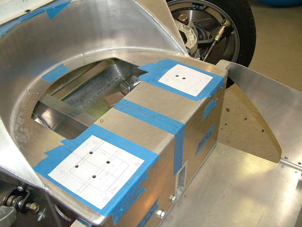
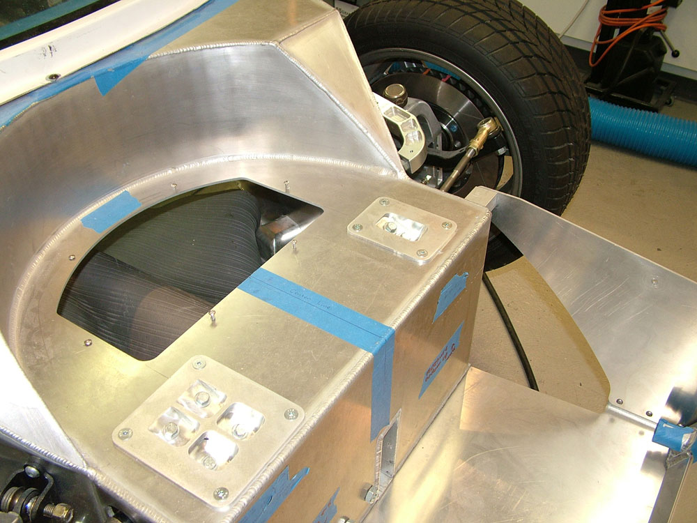
AC Unit
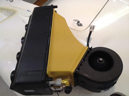
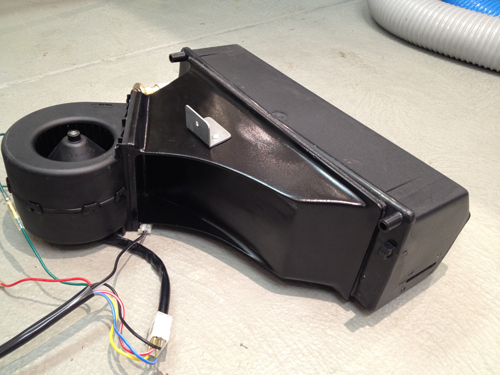
I decided to make a custom AC unit so that I could tuck it up and out of the way. To do this I purchased a good SPAL blower motor and evaporator case and begun to make a fiberglass transition duct. This allowed the blower to sit up in a triangular portion of the passenger side of the under dash structure.
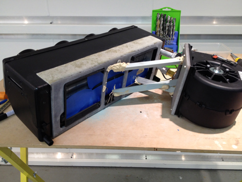
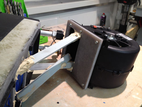
The temporary "sticks" aligned the blower and evaporator so that they fit under the dash perfectly. I then constructed a fiberglass duct around them.
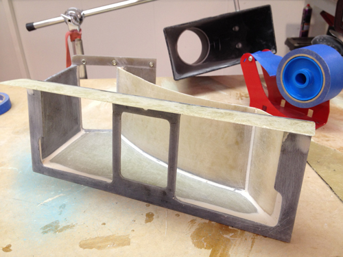
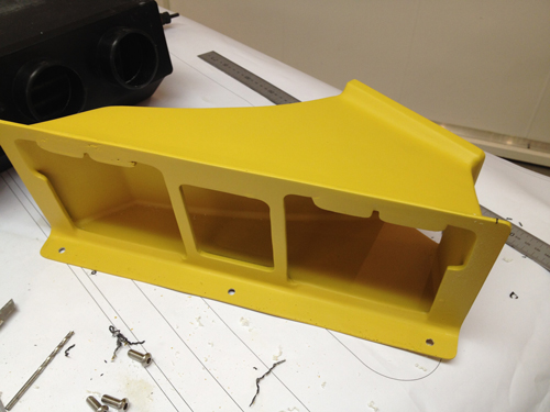
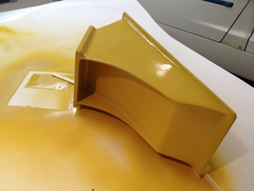
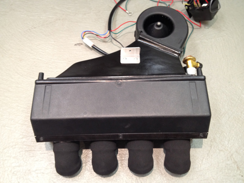
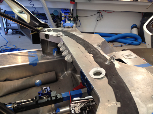
I then constructed a plenum chamber for the evaporator to blow into and distribute the air to the side vents and center dash outlet. Covered in foam to insulate the duct it has angled foam outlet faces that seal to the chassis to direct the air to the vents.
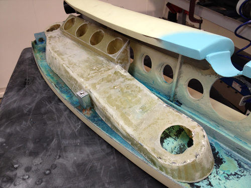
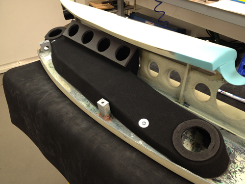
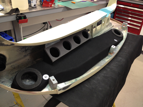
The duct lines up with the chassis points shown below. The air comes out of the evaporator, into the plenum duct, out of the center duct or down into the chassis through ducts to the LH & RH vent outlets. In this way dash removal takes only 3 bolts and the eventual harness connection. No duct connections are required and the AC unit is not disturbed.
Update : 12th May, 2012
More Interior Work
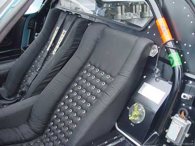
Decided to fit the Schroth 6-point belts. Fair bit of work to get the mounts in and meet the Schroth installation guidelines but got it done. Decided to use another bar like Tom to attach the shoulder belts properly. Welded on stays to stop the belts moving out of position.
I then checked the belts for correct hip and shoulder position. I only have a 30th percentile test subject but it seems to fit fine!
Update : 12 September, 2011
Seats, Door Catch and Pedals
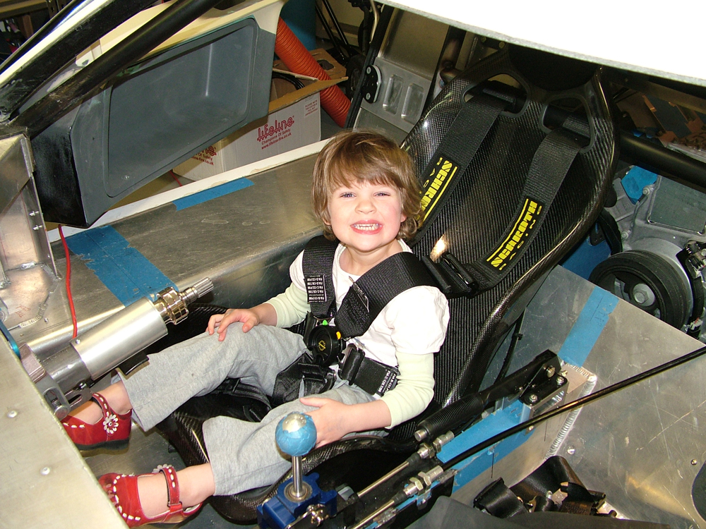
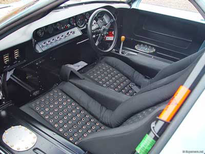
Being tall and not wanting gurney bubbles has meant that to wear a helmet on the track two sets of seats will be required. A set of trimmed authentic GT40 leather seats and a set of bare bone jarring carbon ones! I fitted studs to the floor in the same positions to fit both seats easily without crawling under the car to change them. The carbon ones below worked out really well. With the base of them 3mm from the alloy floor I have good head room with a helmet.
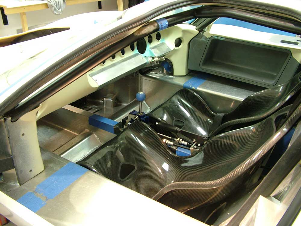
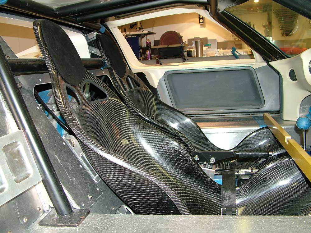
I have also fitted the crutch and hip Schroth harness belts. What a job to do correctly, I see why Tom spent so long organising his! Just need to plan the shoulder belts now and may have to employ some outside help. I have also fitted the bare seat frames for the padded leather grommet seats to check for space and alignment, these now need to go to the trimmer.
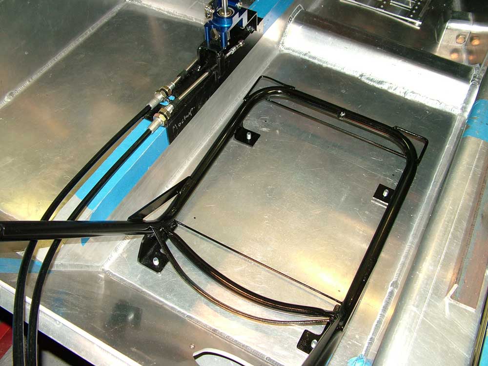
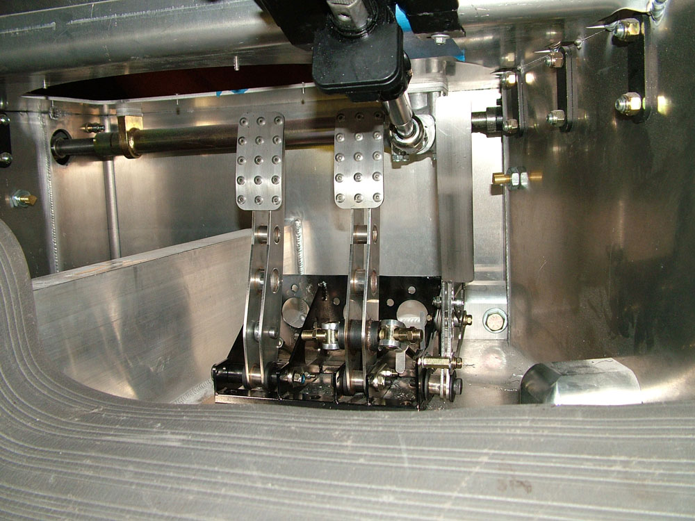
Shifter support shown above is only a mock-up but the shift cables are connected to the transmission and working.
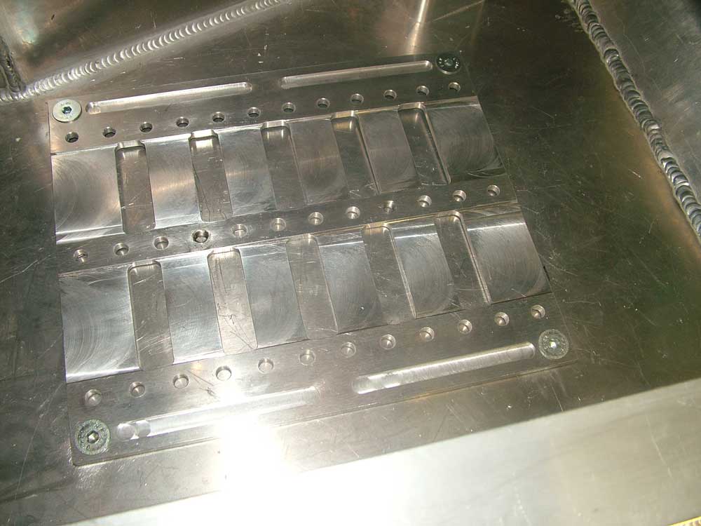
Also completed the door striker support in billet aluminium. Designed to carry load to the cage. It has a hidden fixing to the cage to hold it in position if it is under load due to a side impact.
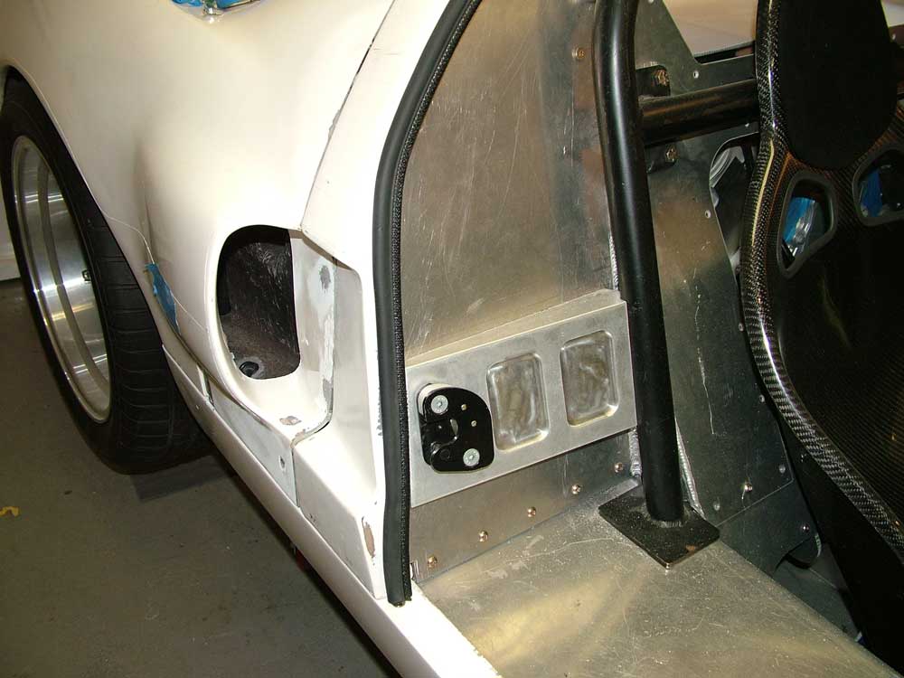
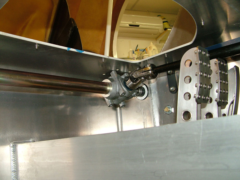
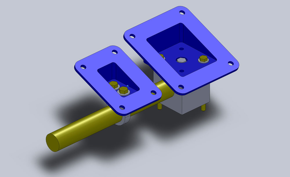
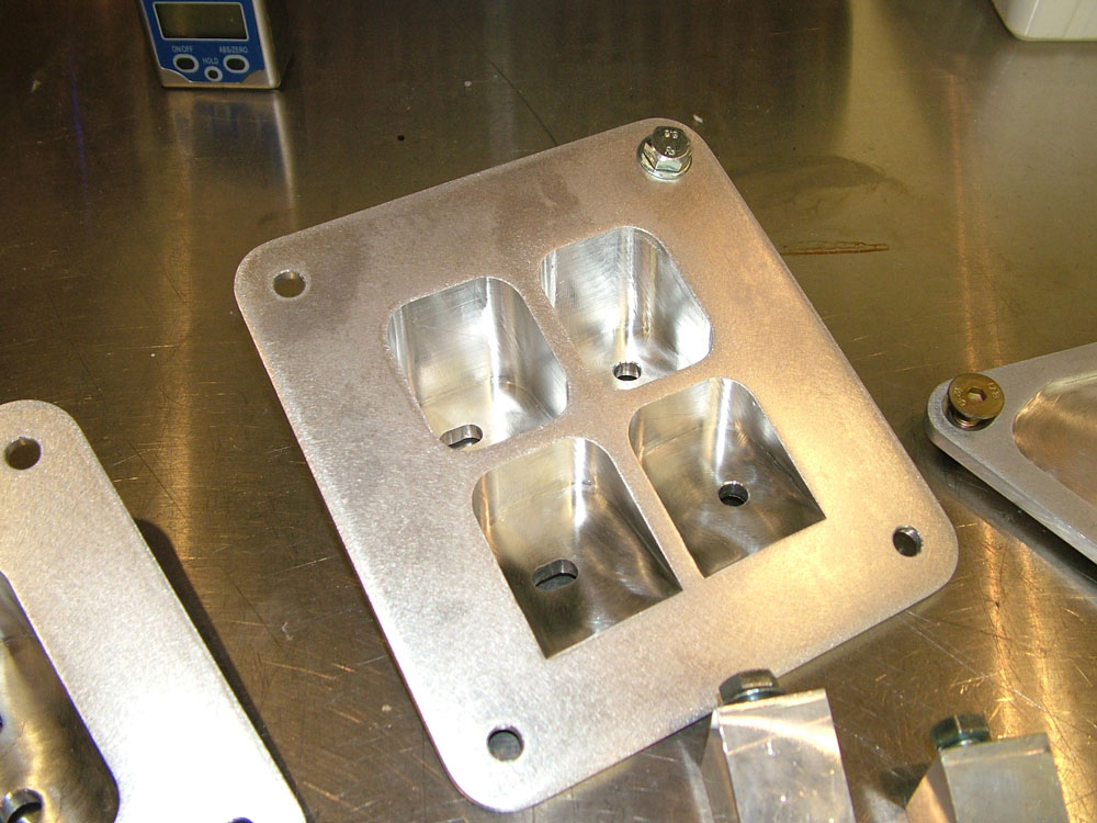
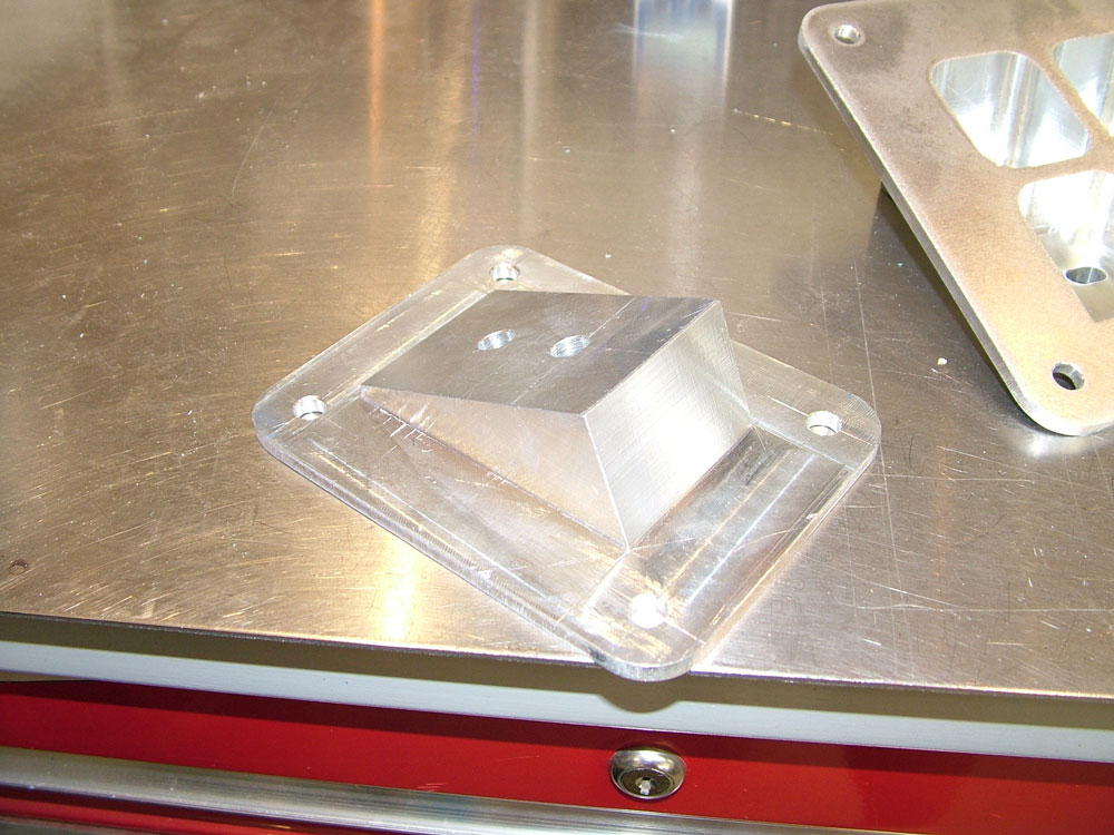
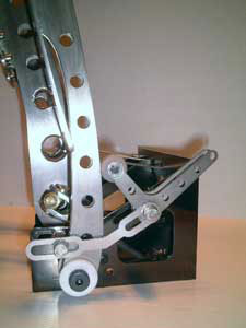
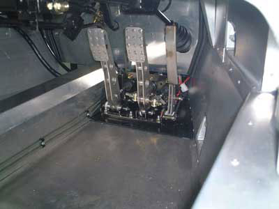
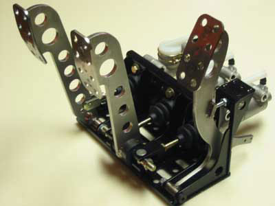
Also fixed the pedals to the floor. I designed and manufactured a billet pedal support that allows 6 pedal positions and also ensures the pedals are level in the vehicle. The floor is slightly warped during chassis welding and this ensures the pedals are not warped and bind when bolted to the uneven floor.
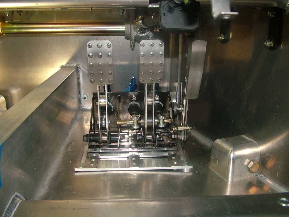
The gap in front of the pedals will not be visible when heat shielding is installed.
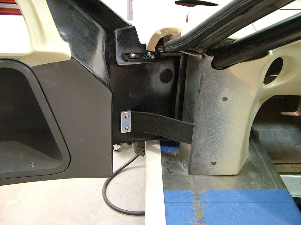
Also fitted a leather door strap from Roaring Forties to the car which I like as its simple, comes with all the fasteners and easy to fit.
Next some rear clip pins.
Update : 11 May, 2011
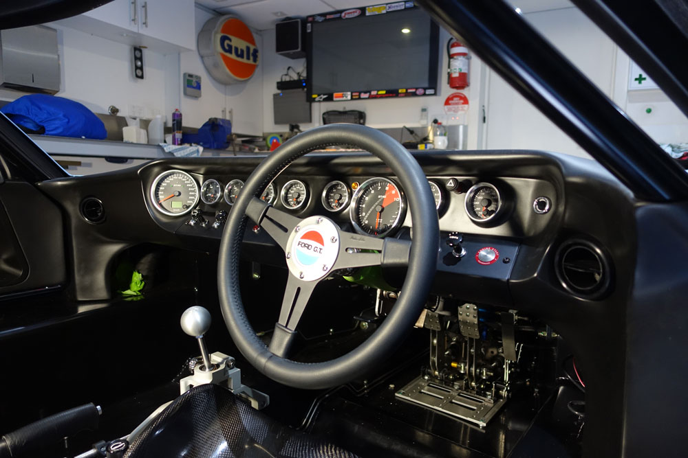
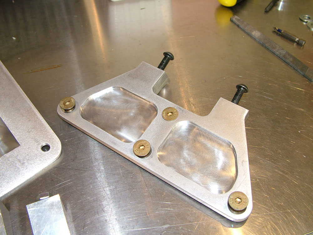
Making the Wheel Boss and Column Adaptor Boss
With the desire to be able to fit an OE steering wheel for compliance I needed to manufacture a boss to adapt the Sparco quick release and fit the Moto Lita wheel. With many various bolt PCDs between Sparco and Moto Lita it was a bit of work!
The alloy cover added to the column will be anodised black.
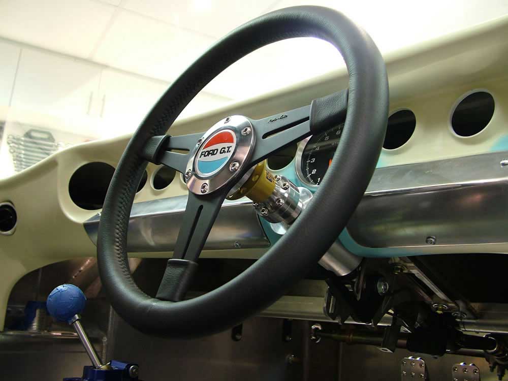
I will be manufacturing a cover for under the column to hide all the sharp edges from legs. I would also like to add one indicator stalk somehow.
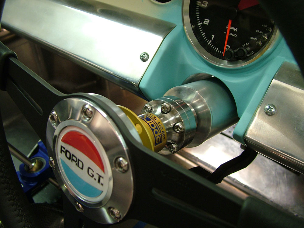
Anyhow now done, just need to get all the alloy parts anodised flat silver and the metal parts plated. Also thanks to DRB for the Ford GT badge, diameter is a good size for this Moto Lita Wheel.
Update : 30 December, 2010
Time to Work Out the Steering Column
The problem here are the things I want!
1) ADR compliant column (a column from a newer Australian vehicle)
2) A fully adjustable column (reach and rake). Mainly due to the fact that building this car with a driving position that is less than ideal would bug me and I don't yet know what a good driving position is!
3) I need a lot of foot well room (size 12 feet) and these columns can run low under the dash causing foot clearance issues
So the fun begins.
I have chosen to use a column from the current model Australian Ford Falcon/Territory. Now some people have said it will not fit so now I had to use it! What you can see in the picture is a few columns I was able to obtain (I have 3 as I was sure I would destroy a few along the way).
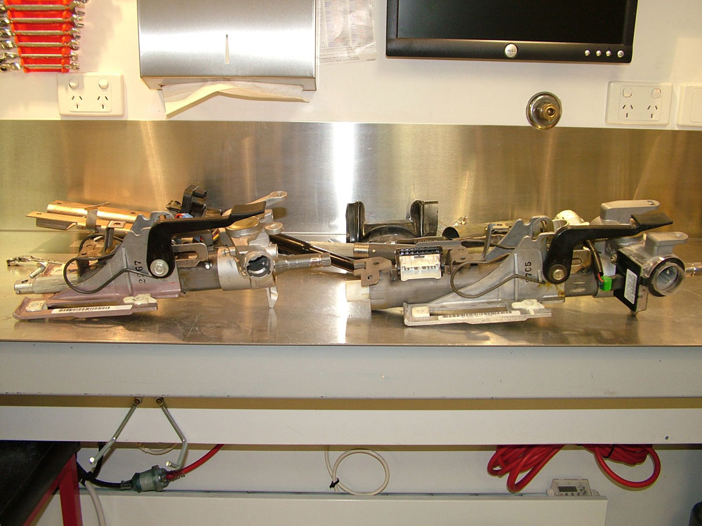
Below is one of the many OE sheet metal mounts and columns I have (this rusted one is for trial use only). By using this I can ensure that the shear away plastic mounts on the column are fitted to a fully compliant OE structure and the column will behave in an OE manner in the unfortunate event of a collision by shearing off the mounts. Very important for ADR compliance.
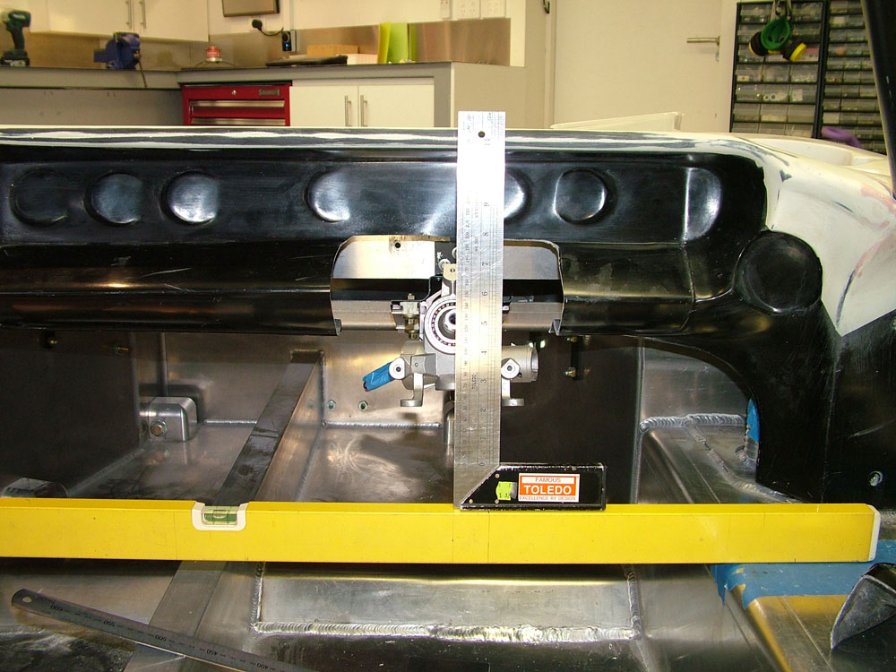
One of the first things I noticed when planning the rack fitment was that if I was to rotated the steering rack about the centre of the rack I could push the column up higher in the foot well without changing the RCR steering geometry. I purchased a set of pedals from Jim Cowden (really are terrific pedals, not sure if I will use the accelerator yet) and below is the result if I leave the rack input shaft horizontal. You cannot drive a car like this!
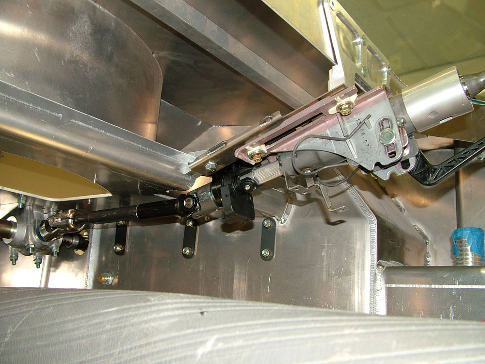
So I began planning to rotate the entire steering rack and things looked a lot better. RCR had spacers fitted and this is a godsend. It allows approx 22 degrees of rotation. Now to rotate the steering rack permanently.
CAD to the rescue (I have no imagination and have to design everything first!) and the following were machined up from 6061T6 alloy and fitted.
Ribbing was added while I milled them to add additional strength.
Both brackets have exactly the same angle.
Drawings were created to ensure the rack position was kept correct when cutting the chassis. Mark 1,000 times and cut once for me!
When assembled the wedge mounts do not look to out of place.
They achieved the angle I was looking for and pushed the column high up in the foot well. The non nyloc nuts are for temporary installation only.
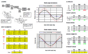
Next job was to check the steering column geometry. I spoke to a very helpful engineer that works on OE steering systems and quickly learnt that column geometry and design is a science, what a surprise. Ensuring correct steering feel by controlling shaft angle deviations and shaft relative velocities with correct joint phasing and phase valley centre positioning is critical. Using a proprietary software program all the correct steering angles and phasing was calculated. Angling the rack was the best thing I could do as this provided a good setup where the steering column angle was very close to the rack angle. With almost equal angles my steering was reported to be better than most OE setups so I was very happy with little joint phasing required.
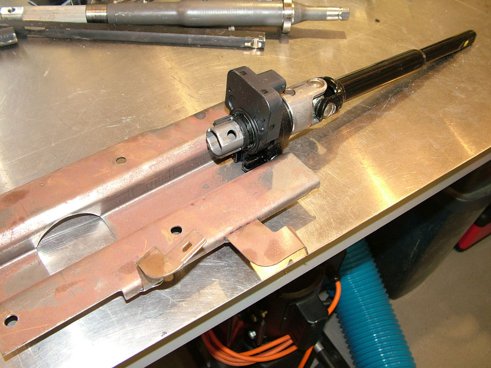
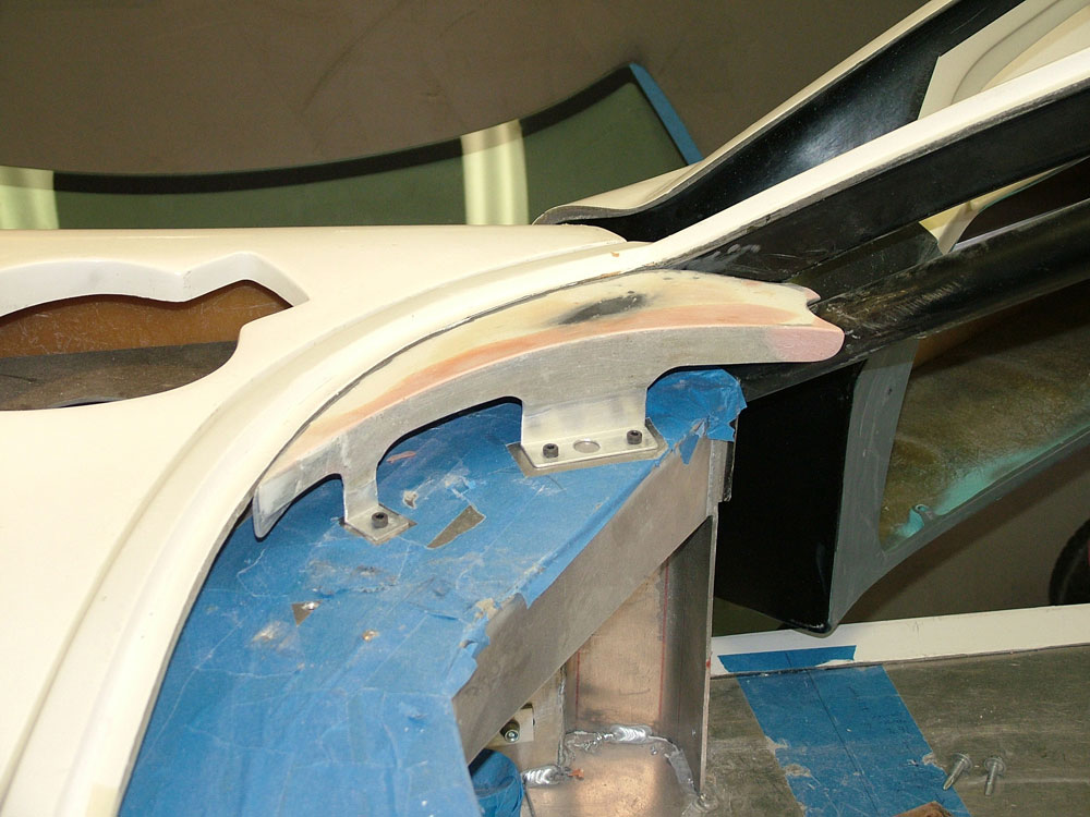
Now to mount the column. I also designed a bracket to mount the column at the optimum angle. As the column is adjustable I simply ensured I could get full range of motion. The brackets were designed to hold the OE column mounting plate and also strengthen up the RCR dash cross member which can flex. Tying the front of the dash to the chassis via the OE sheet metal structure has resulted in a VERY rigid mount.
Mounts in place, you can see the small rear ones I also machined up. A cut was made between these to clear the column. The bracing affect of this very rigid OE structure more than accounts for this material removal.
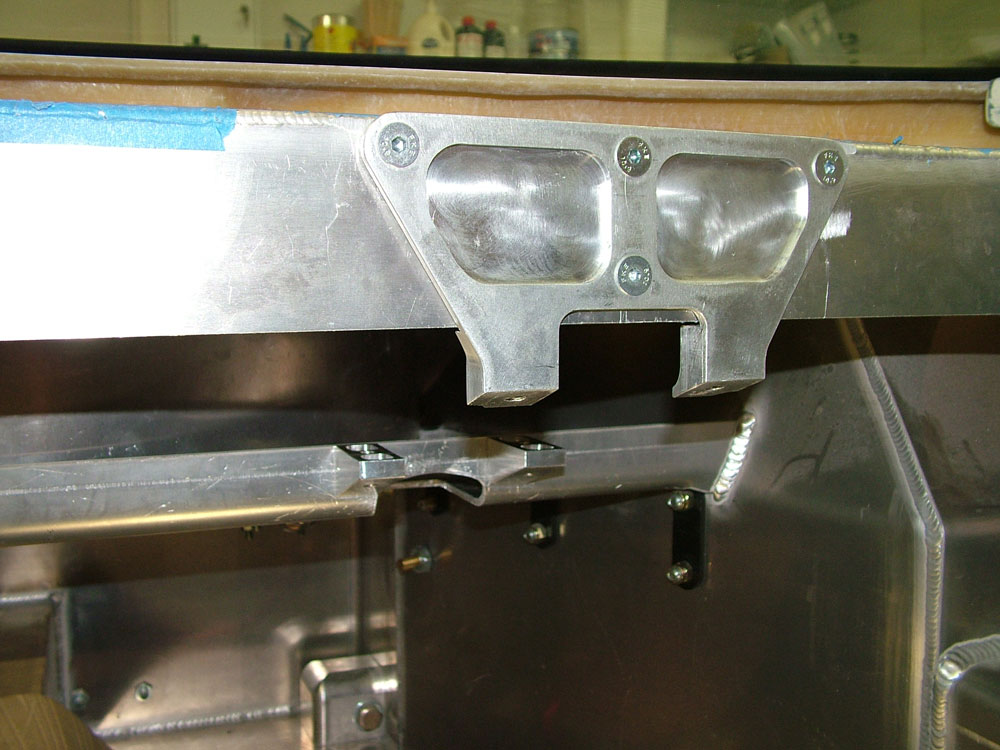
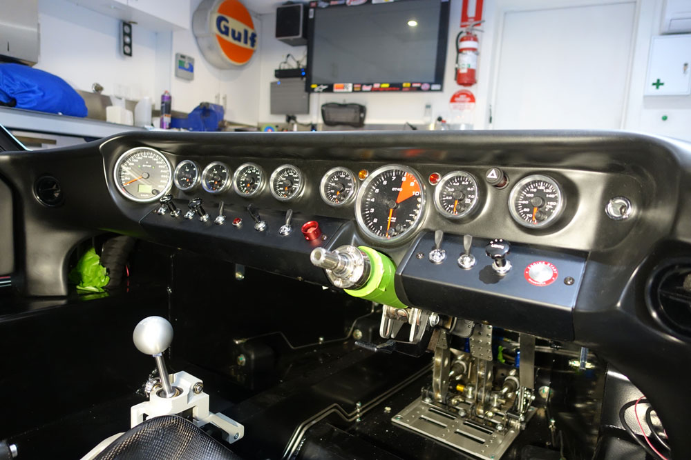
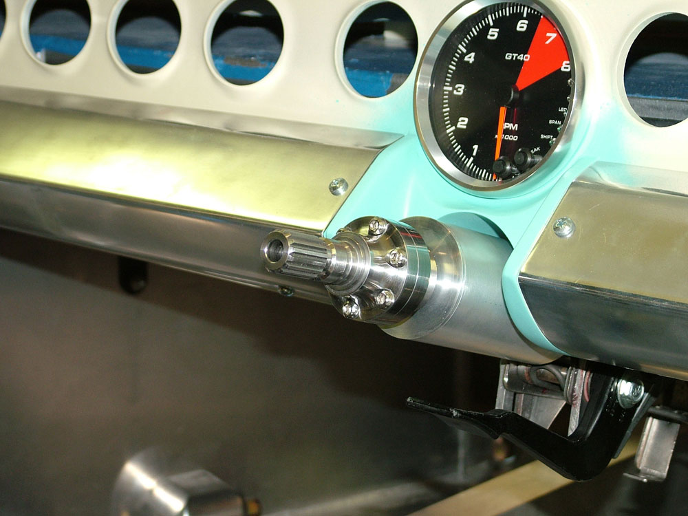
Column fitted. The ignition key will be on the dash or centre console and the ADR requirement for a anti theft lock device will be fitted to the transmission as permitted in the ADR's. I did not want a bulky column in the car as it just looks out of character.
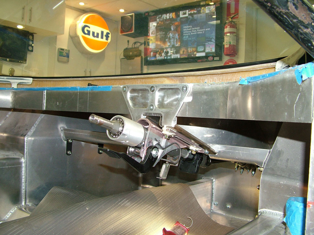
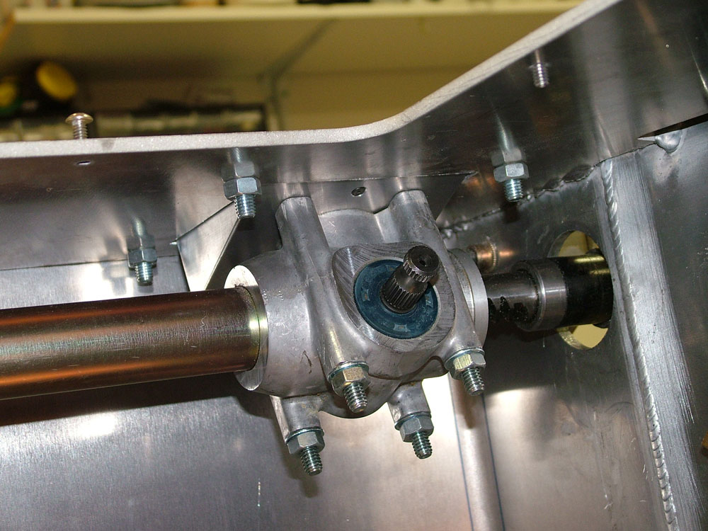
The column fits very close to the top of the foot well. All that is left to do is get the shaft welded by a certified company. You can see the splines alloy OE collapsible section of the column. I also have a second telescoping section near the rack to allow for the rake adjustment of the column and add additional intrusion protection.
The steering angle sensor (black thing near the first joint) and some of the redundant brackets may also be removed later depending on the column dressing fitted. All in all the steering now looks very neat, will be compliant and offers full adjustability. A small clean up around the dash (blue below) was all that was needed.
Adjustability is great. With the rake and reach adjustment available removing the wheel could possibly be be avoided.
This took a lot of time but was important to me to get right. I have seen the fully compliant RF steering system and was most impressed, so they set a high bar for me to aim for. An OE Ford steering wheel fits perfectly for compliance measures as well.
Update : 24 October, 2010
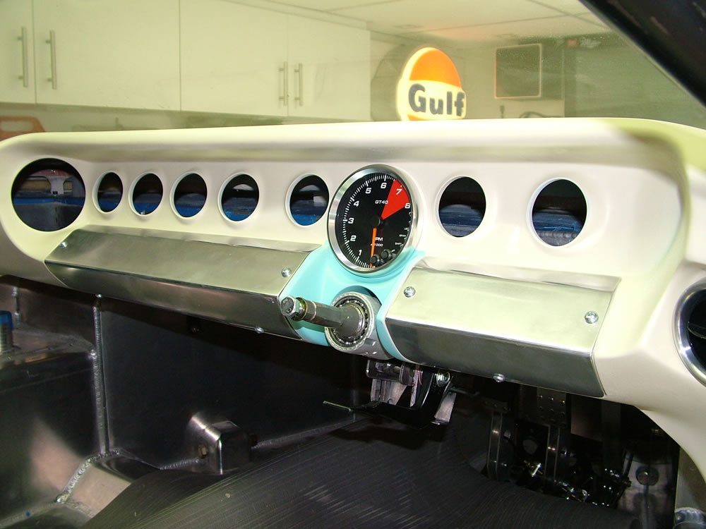
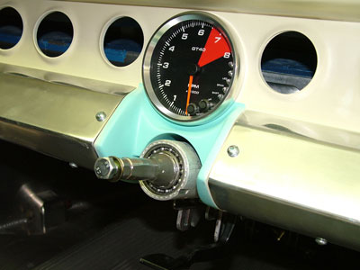
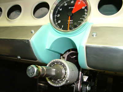
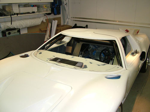
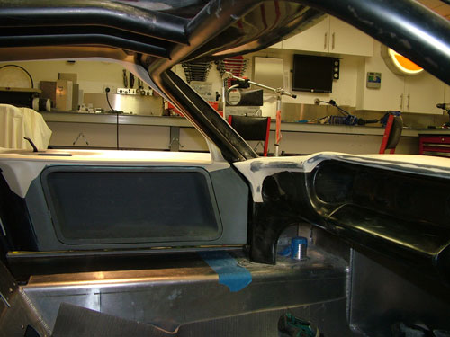
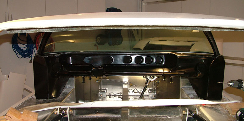
More Work on the Dashboard
So after getting an RF dash and working on the top it was time to look into the gauge and column area. I tacked a temporary column in position and as can be seen in the image the centre of the RCR driving position is different to the RF (possibly due to the RCR having a larger drivers side area than the passenger side), time to cut and shut the dash.
After much cutting and glassing it was time to cut the holes for the gauges.
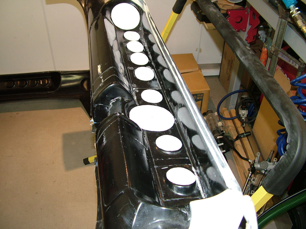
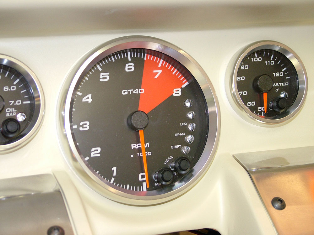
Some may notice I have added an extra gauge on the left, needed one extra. A quick trial fit of the gauges and all was looking OK. I purchased some custom manufactured gauges and sender units from the USA that are all digital and have some custom additions like high beam indicators etc. These were also tricky to fit due to the way they attach with a small threaded ring on the rear but the job was done. Here you can also see that I have inverted the fiberglass lip under the dash to give a little more leg room.
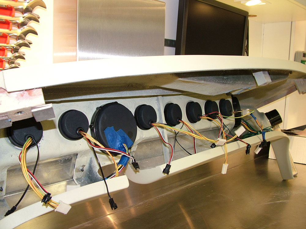
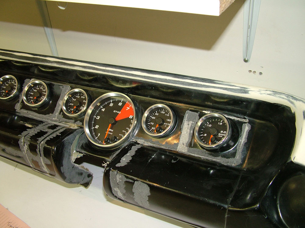
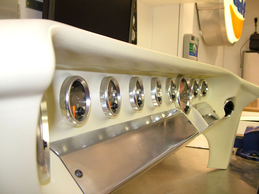
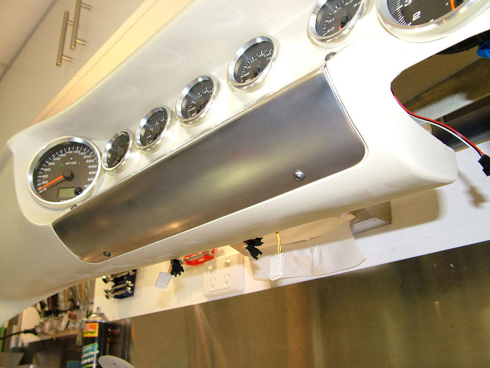
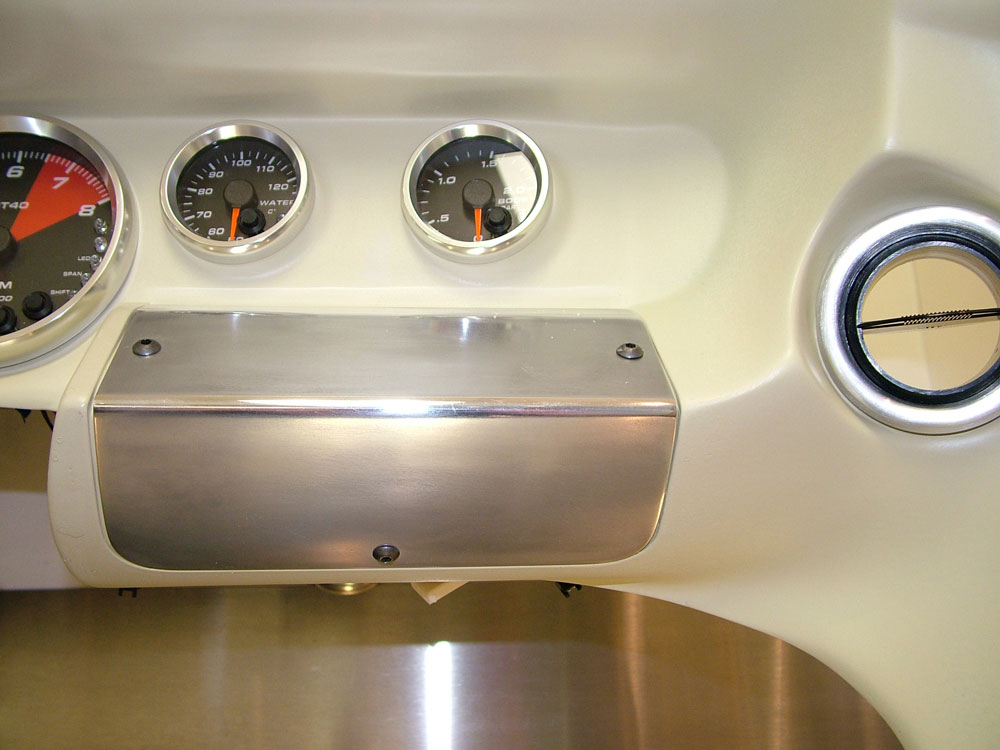
Next job was to make the alloy plates under the gauges and prime up the dash. cutting, bending and rolling the alloy plates was a PITA! I had this vision of a pair or perfectly shaped plates when I started and I was going to be dammed if this is not what I finished with! After many hours of metal rolling (I have one of those 3 in 1 metal bender, guillotine and roller units) I did get what I want. Its funny, only people who have made these will possibly know how the shape is a little tricky to get right, especially the curve under the dash.
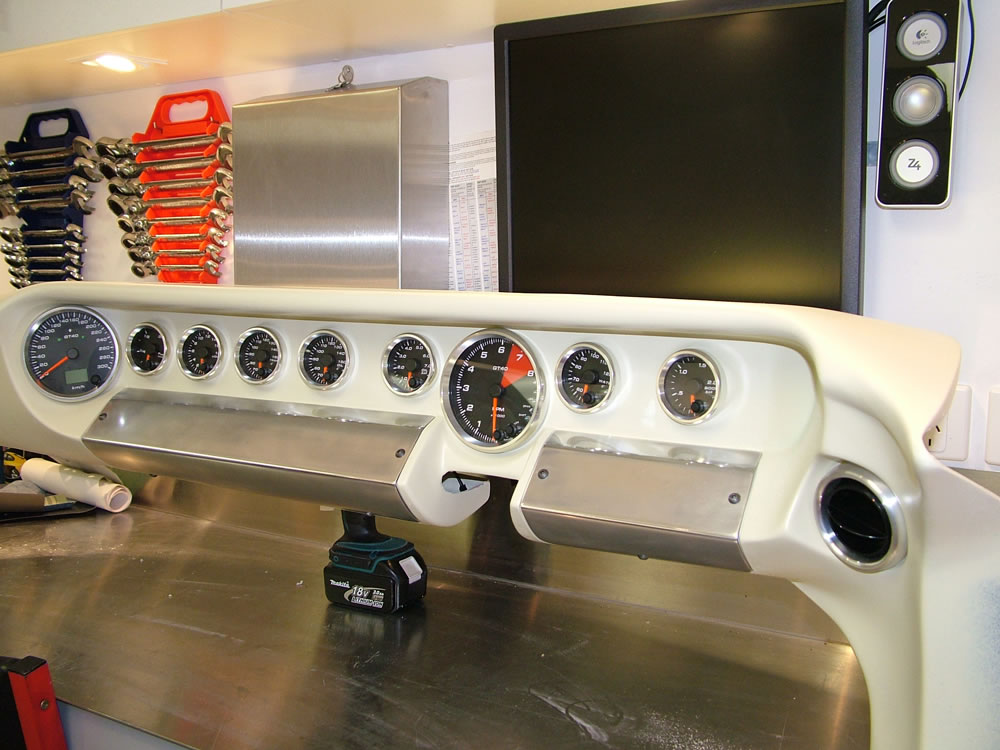
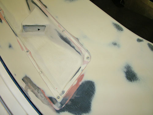
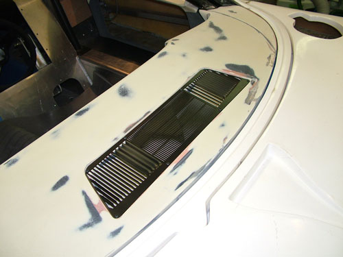
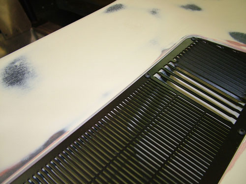
I also inserted some AC vents into the dash. The plates may be black but they are polished to check shape and bend continuity. I also wanted the top edge of the dash to be straight (some have a dip down in them that looks like they melted down) this took some work.
Job done on the plates time to look at the steering column.
Update : 10 October, 2010
Work on the Dashboard
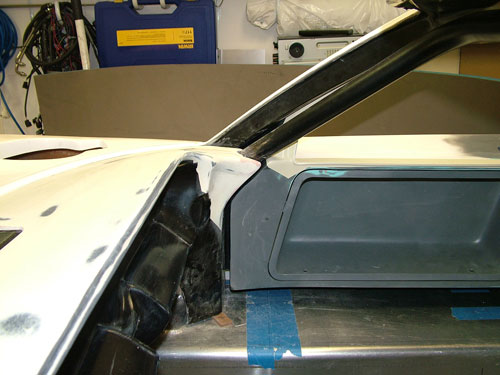
I have had issues with the RHD dash supplied with the car. I purchased one from RF in Australia and then have set about making a few changes. I wanted to have the ability to remove the dash without taking out the roll cage. So I made fixed side parts as I have seen others do. I had thought of it before I saw it from others, I promise.
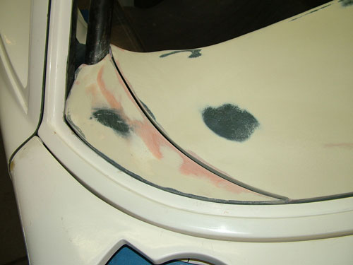
I also did extensive work on the dash area to perfectly match the base of the window. I really do not want to see the lip of the spider supporting the lower edge of the glass.
Work was also done to perfectly fit the defrost grille. I will be painting this dash and have a later addition to comply with ADR's.
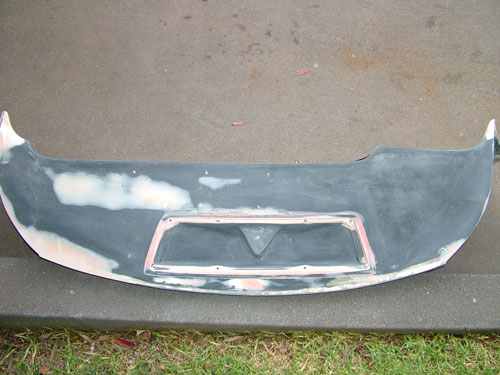
When fitted the top of the dash is much better. It also was modified to better line up with the doors.
Now I might think about seat, steering and pedal positions.
Update : 2nd June, 2010
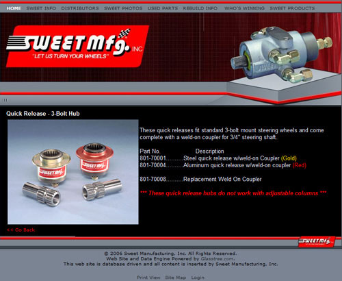
Sweet MFG quick release
Trying to locate the following part to adapt it to what I hope will become a rake and telescopic adjustment to the steering wheel in my 40. I have a very compact current production GM steering column used in Australia that may fit. As soon as the dash is positioned this will be attempted. I'm looking for the 801-70004 with the loose weld on adaptor as shown below to add to the column.
Update : 12th August, 2008
Dash panel fitment
After receiving the RCR LHD dash in error with the car, RCR were kind enough to send out a RHD version. However fitment began to identify some issues with this dash. Its design is different to the LHD in a few areas. The lower extensions are much shorter and the fit to the base of the windscreen not ideal. It has an upward lip at the window rather than a corner down. It may have been my fitting approach but I did not like the differences. The LHD dash looked like a better fit. It had longer extensions down to the tanks and I also did not like the "droop" in the binnacle cover, you can see it below.
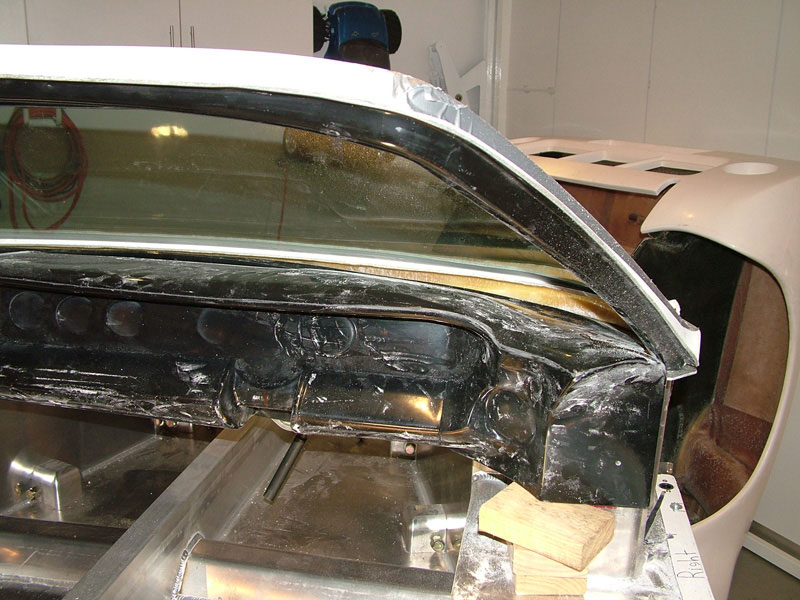
RCR RHD dash panel.
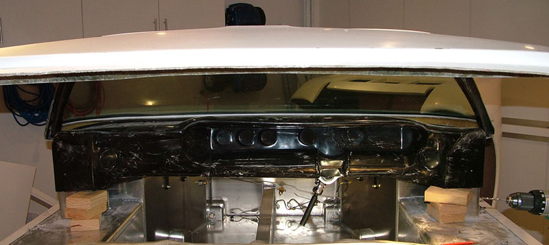
RCR LHD Dash panel.
I contemplated cutting the LHD up and putting the RHD gauge area in it, but before I did I visited Roaring Forties, they were as helpful as ever and I purchased one of theirs and its very similar to the RCR LHD one, very happy. You can see them all below.
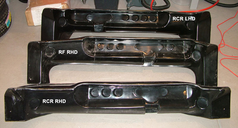
The photo makes them look different in size but they are quite close.
RCR LHD, total width 1,452mm with the steering CL 236mm from the CL of the dash.
RCR RHD, total width 1,475mm with the steering CL 228mm from the CL of the dash.
RF RHD, total width 1,460mm with the steering CL 215mm from the CL of the dash.
Needless to say the RF dash will be fitted. It may need some work at the steering wheel exit but that's OK.
Update : 20th May, 2008
Pedals
The pedals I plan to use are manufactured in Australia by Jim Cowden from Australian Engineering. They are made differently to the RCR items and are local. (316 Pedals and black nickel steel frames). Uses a 5/8 front and ¾ rear master cylinder. Images are below. I have not purchased these yet.
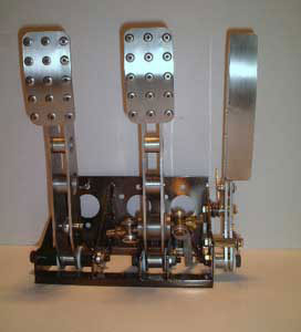
The RCR item is shown below. Also well constructed.
The accelerator pedal will need to be electronic due to the fly by wire engine being used. Part numbers for the accelerator are varied.
Holden quoted part number - 92189338
Forums quote for the six pin 92189345 and an eight pin 92188387. Need to work this out!
Update : 15th May, 2008
Interior Concept
The interior of the car will follow loosely the original racing cars. It will have a spartan interior but will have to be road legal, and this will drive some changes.
GT40 P1075 interior shown below.
My vehicle has the full roll cage option and will be fitted with a centre shifter. It will be RHD for Australia!
Update : 5th May, 2008