
Put the Engine Back In for the Final Time?
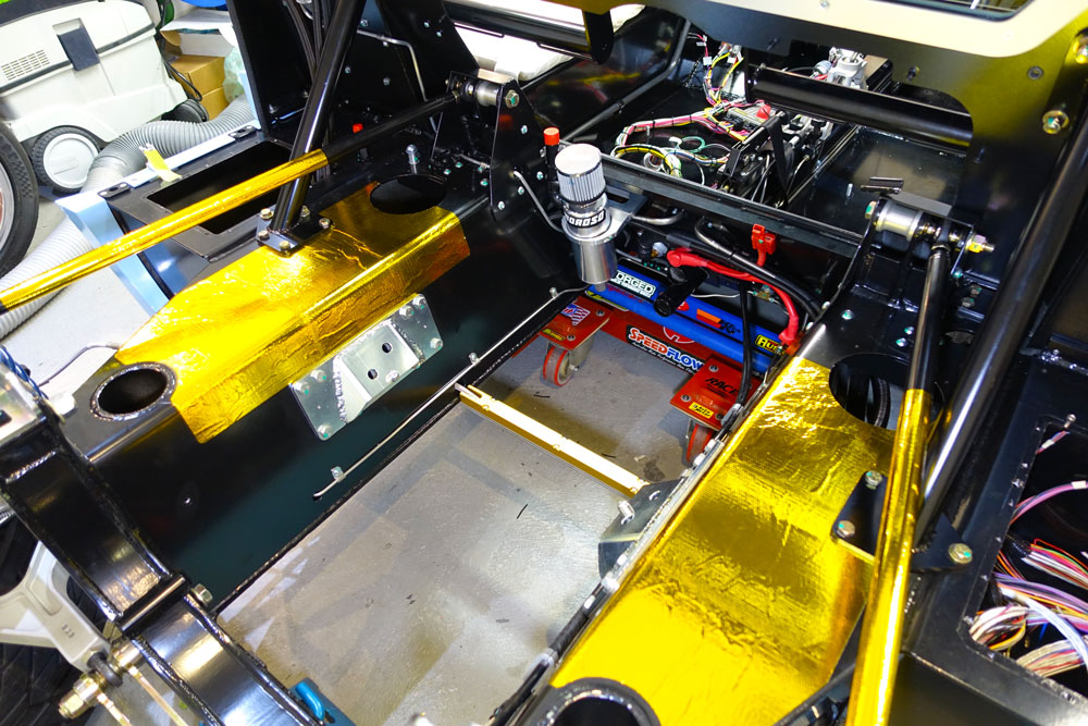
Well a lot of work going on. With the wiring done around the engine it can be installed for hopefully the last time. All parts get their final finishes. Before installation I wanted to try to minimise as much heat into the chassis as possible so I went crazy with DEI gold heat reflective film!
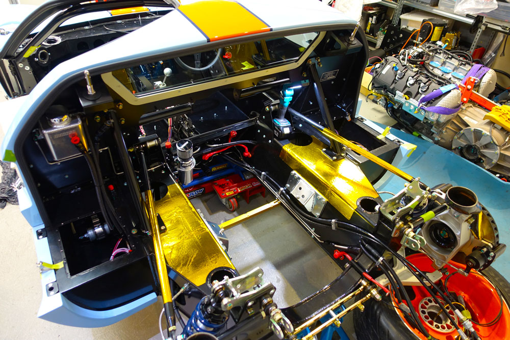
I also did a little work on the radius rod supports.
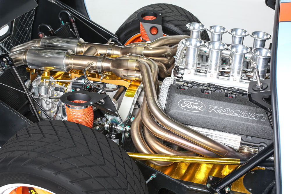
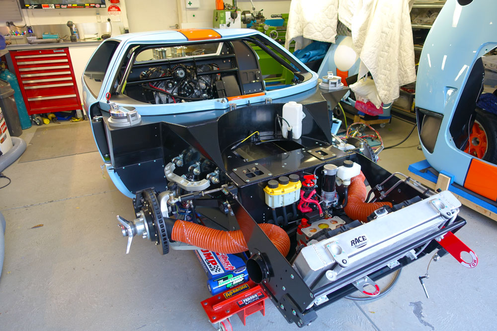
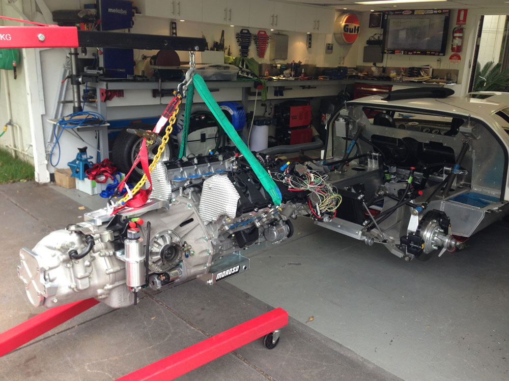
Then it was time to install the engine and exhaust.
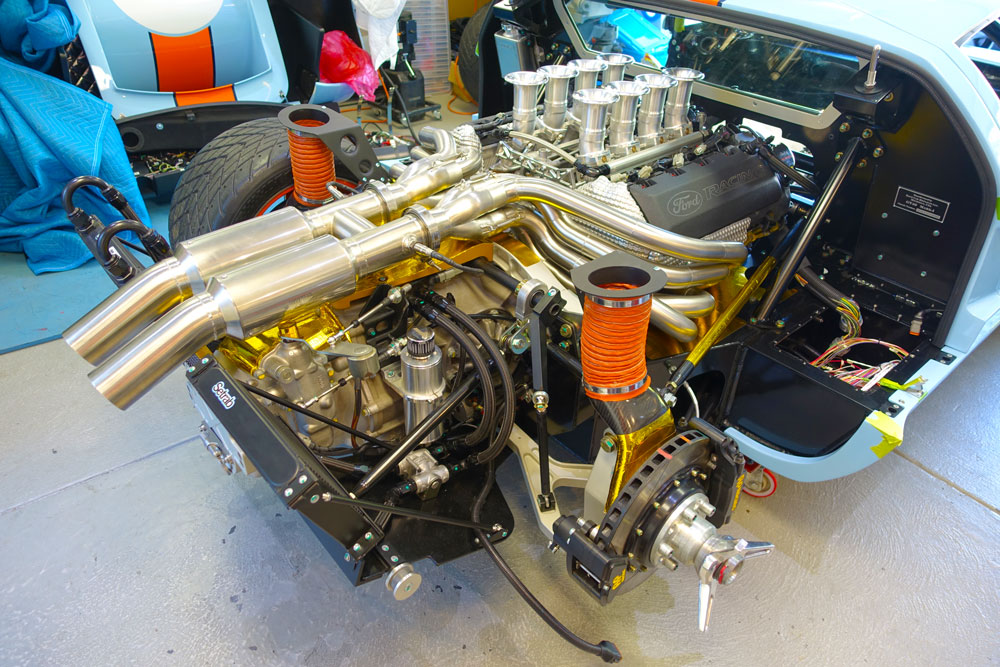
It all went very well. Its a very tight installation but that is the result of a Coyote and Ricardo in an RCR chassis. To get the engine out the headers have to be removed so I hope all is well.
I still have the wiring near in the ECU box to go but all other electrical is done.
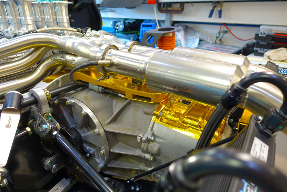
Even though the exhaust is ceramic coated on the inside I really wanted to control the radiant heat on the transaxle. O2 sensors are a bit ugly but really needed to tune.
I moved to the front and with the confidence I have with my skills installed a tow hook. It will be needed I'm sure!
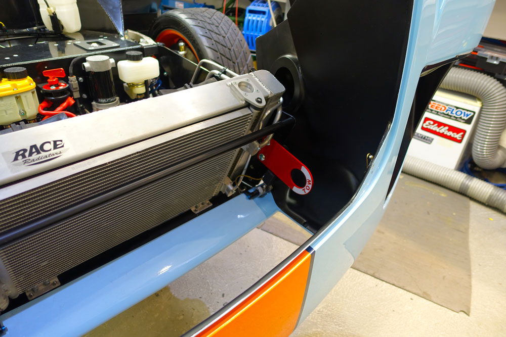
Then I thought that with my luck I will wear it out and installed another in the middle!
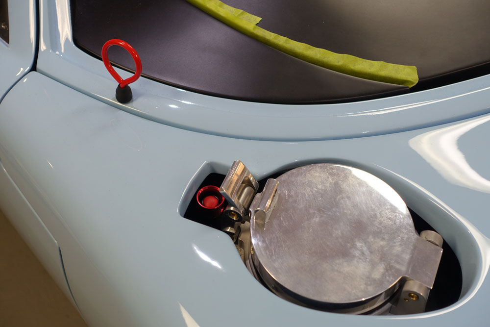
But seriously the one on the left looks cool but the one in the middle is more functional as its in a better position and will not stress the chassis as much as the side one. Also all A/C plumbing is done using as little hose as possible. I then installed the fire extinguisher button (near the filler) and the battery disconnect (near the window).
Brakes and clutch are bled. So now the fun is over, back to wiring up the ECU.
Update : 12th September, 2015
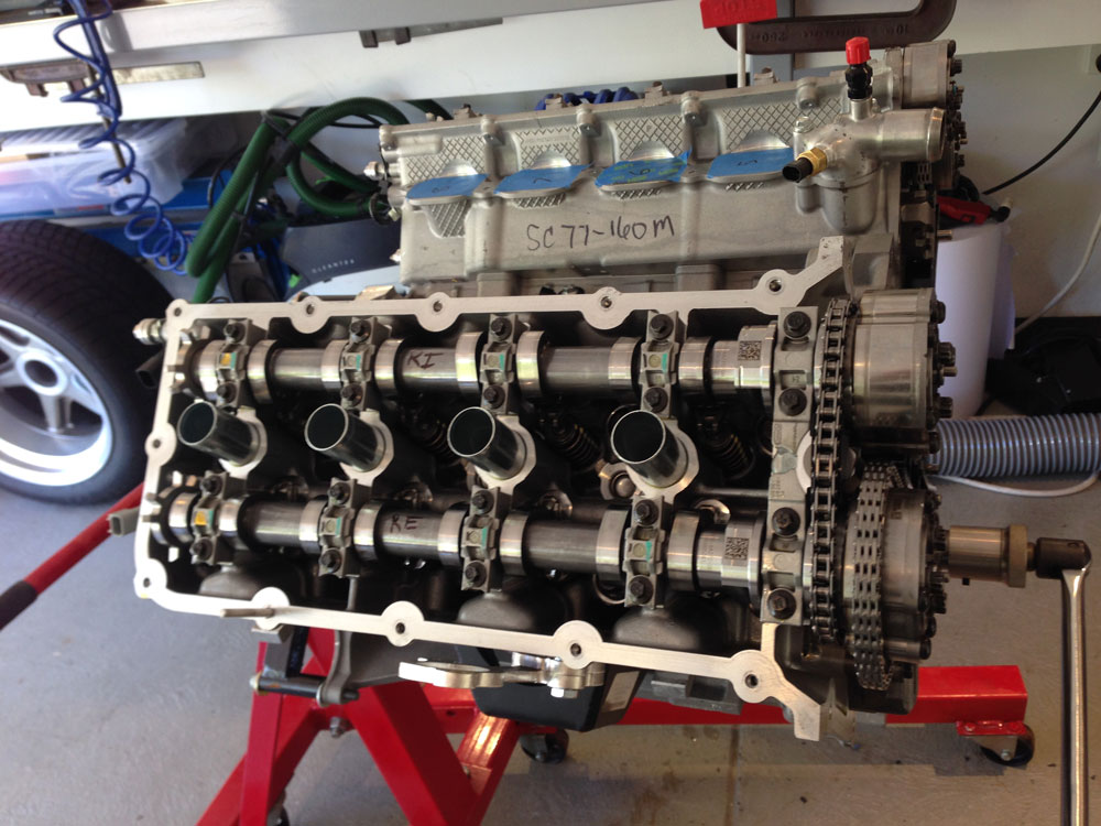
Pull the New Engine Apart!
Decided to fit stage 3 cams and a billet oil pump to the engine. Never done it before and with the help of a mate (thanks Jas) we got it done. We will know when it starts if its done right!
Then it was time to put the clutch assembly on the engine and throw the lot back in the car again.
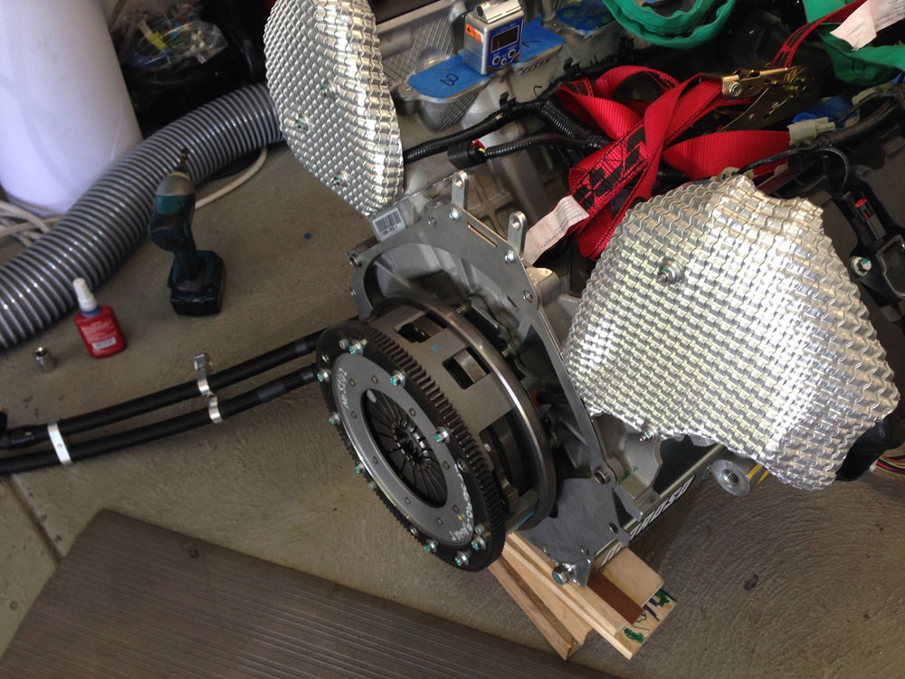
Lucky its a real small drivetrain!
It will come out again!
Really looks great when its back in the car.
Update : 14th January, 2014
Fuel System and Water Plumbing
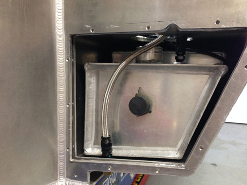
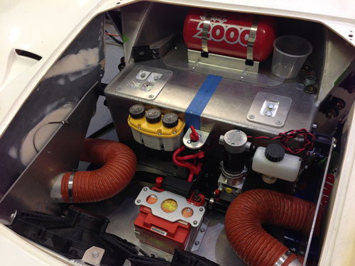
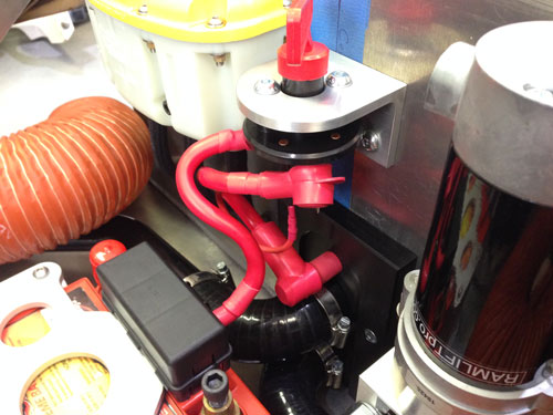
I sought some advice on the fuel system and was happy with the recommendation to fit a pretty simple system. From a pump point of view I opted for a custom in tank solution (passenger side). This is a very neat and simple solution. I have opted to modify the chassis to accept later design RCR separate tanks for a bit of added safety.
The fuel pump was recessed into the tank with some custom alloy parts I made.
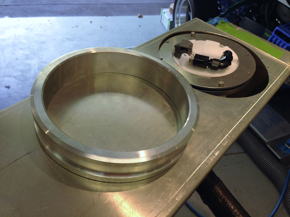
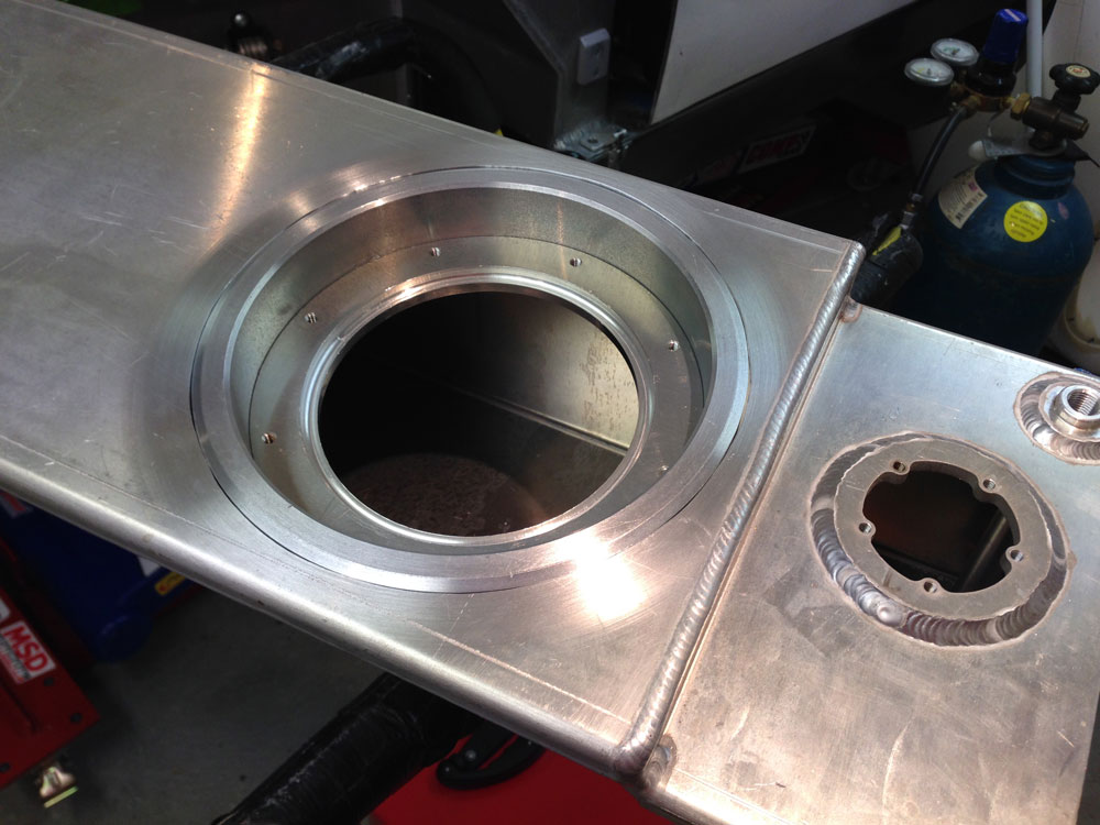
This allows the tank to slide into the chassis.
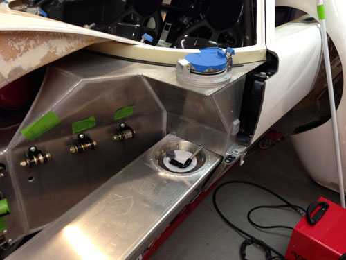
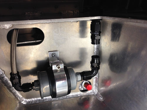
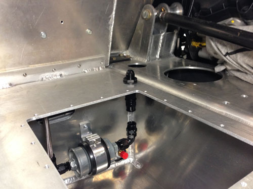
The fuel filter was placed in the compartment behind the tank on the LHS of the car.
The LH and RH tank are balanced with a cross line under the car. It is on top of the stainless steel bar that protects the front of the sump and is protected from the top with a billet alloy bar.
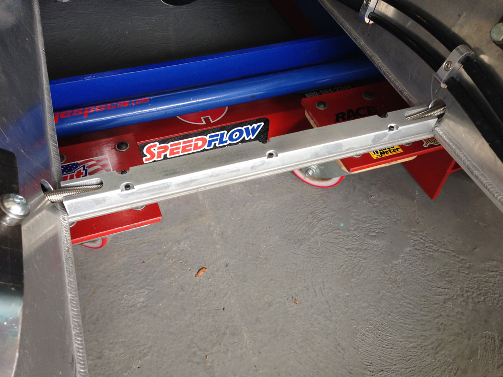
A pump can be added in the RHS of the car to transfer the fuel if it does not siphon to the LHS tank. It probably will not but I would like to see if it does.
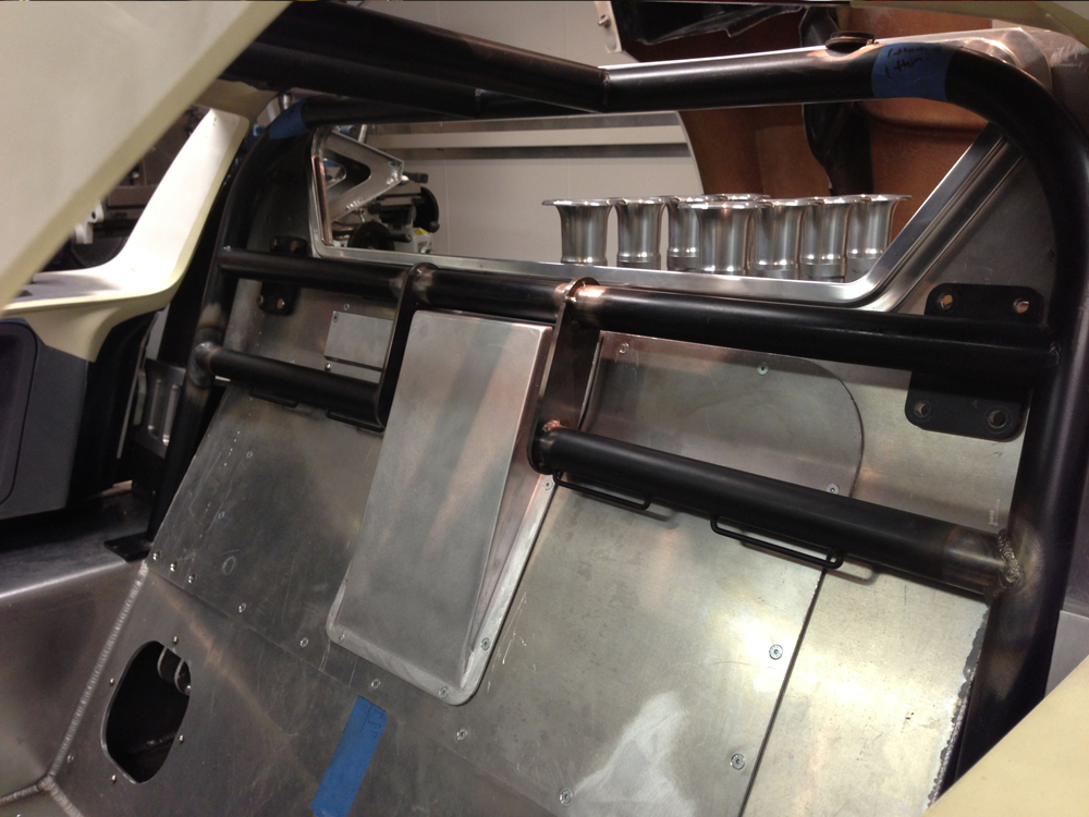
WATER
The plumbing pipes were completed and fitted. The were ceramic coated on the inside and out to limit heat transfer to the chassis.
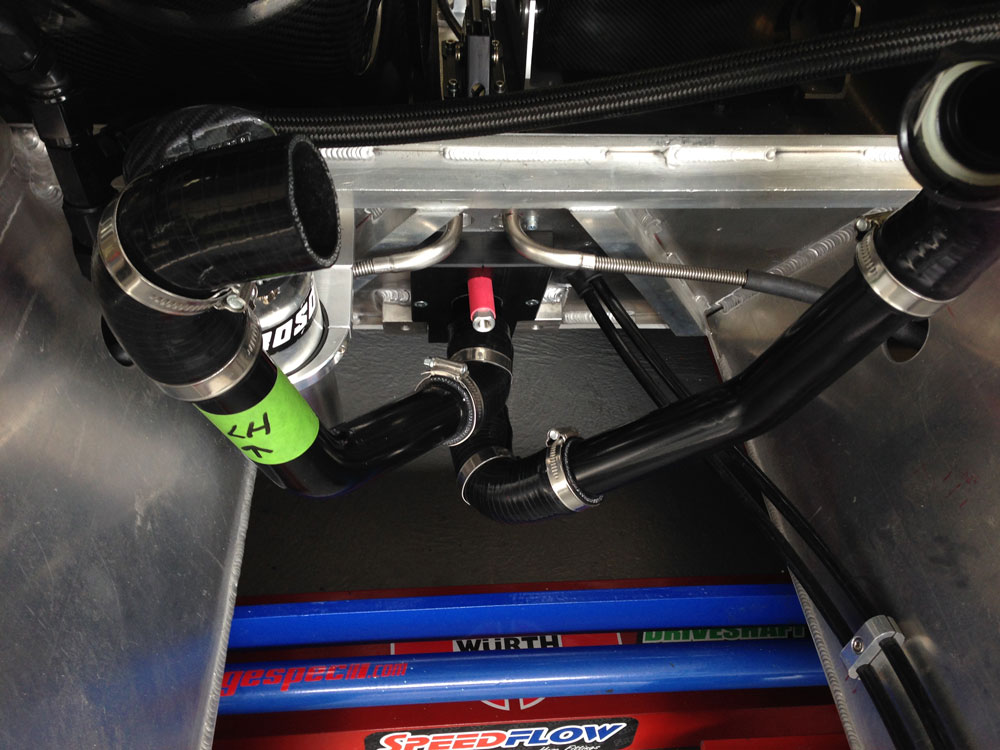
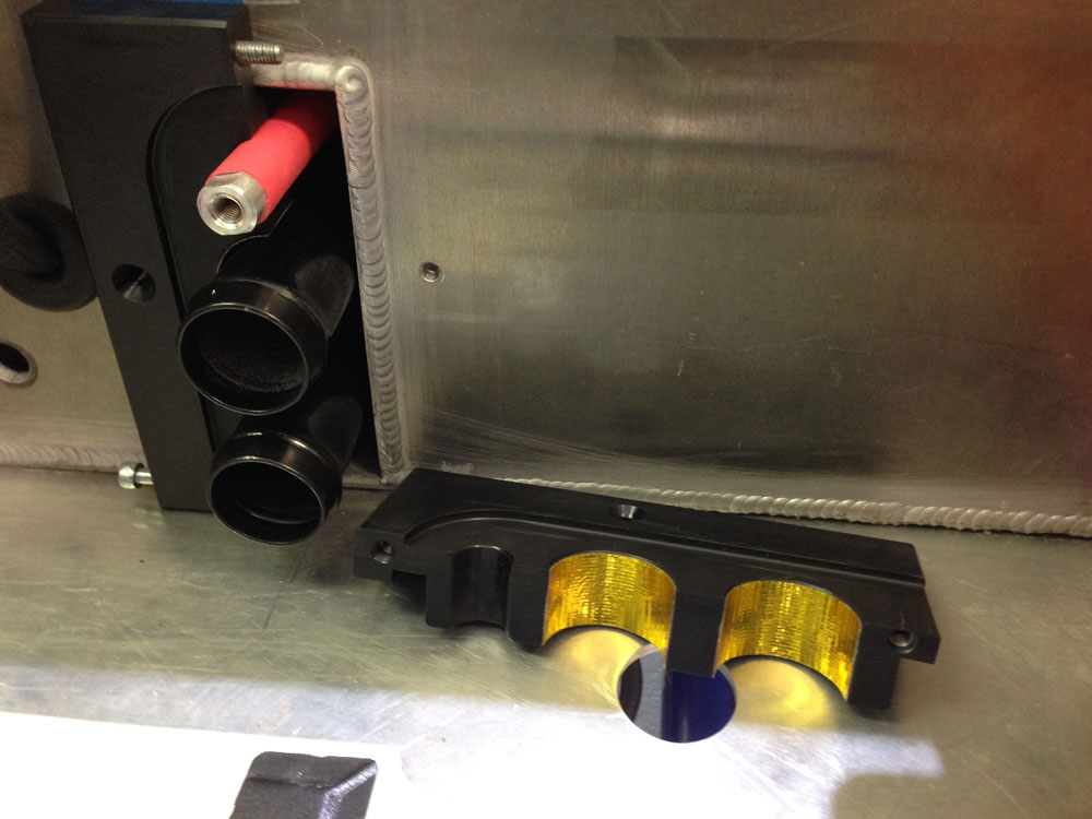
At the front you can see the nylon blocks that hold the tubes securely. The red alloy bar that runs the length of the car is the way I get power from the battery to the alternator and starter. Much lighter and simpler than a copper cable (lower alloy electrical conductivity allowed for).
 .
.
All plumbing installed. As with all GT40's, its getting tight but I'm managing to keep it neat!
Update : 12th January, 2014
Block Plate and Drive by Wire Stabilisation
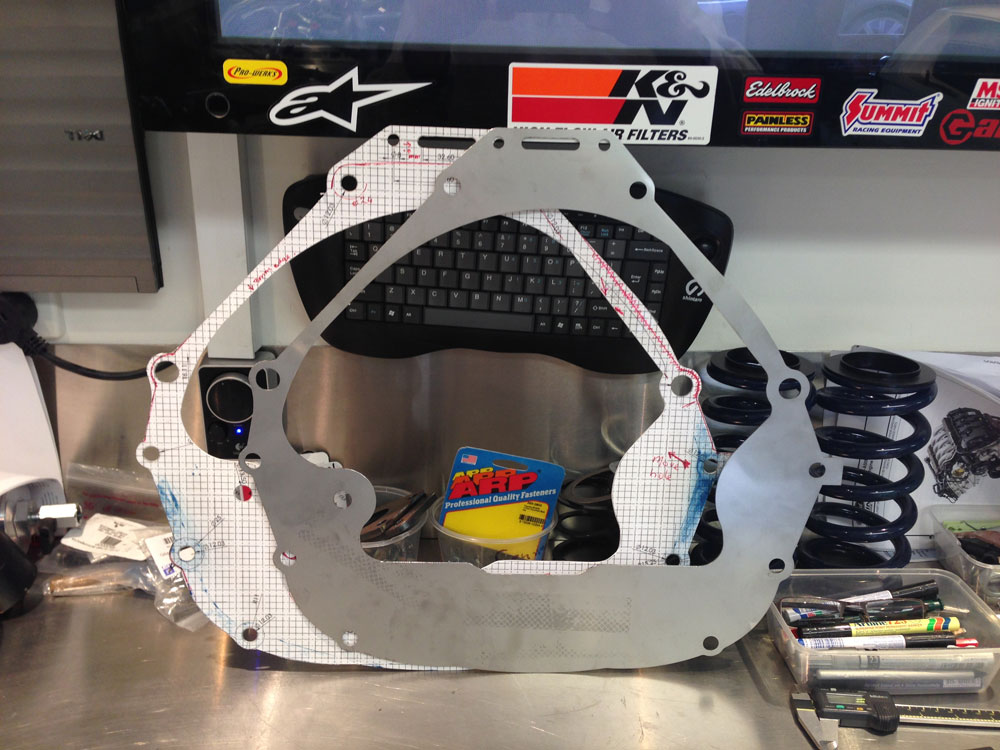
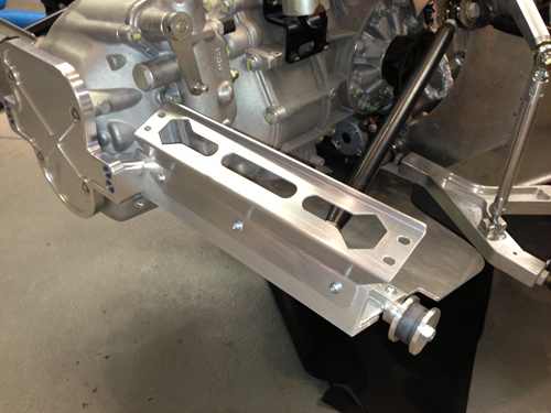
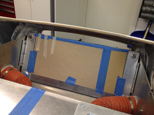
I knew I needed a block plate between the transaxle and engine but was avoiding it! I finally decided to design one up in CAD to have it laser cut. I designed the part and made a template. the block plate may be important to setup correct pilot bearing engagement but I definitely needed it to close up some of the engine and transaxle "gaps".
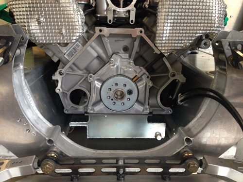
I made a cardboard template from my CAD drawing and then had the part laser cut from 1.5mm stainless steel. OE Coyote one is 1.7mm but I only wanted 1.5mm.
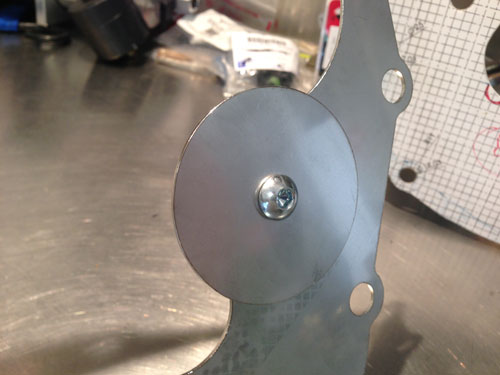
I also wanted to close out the round hole on the LHS of the engine block and a simple circular disc was attached to the plate with a nutsert.
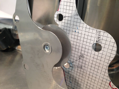
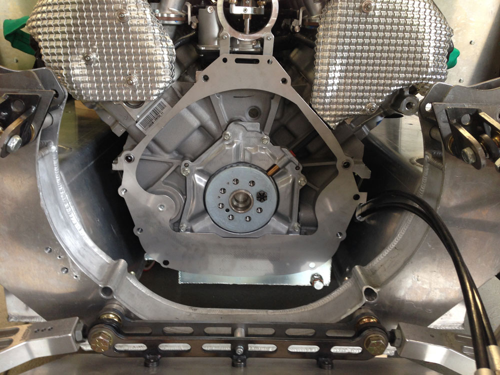
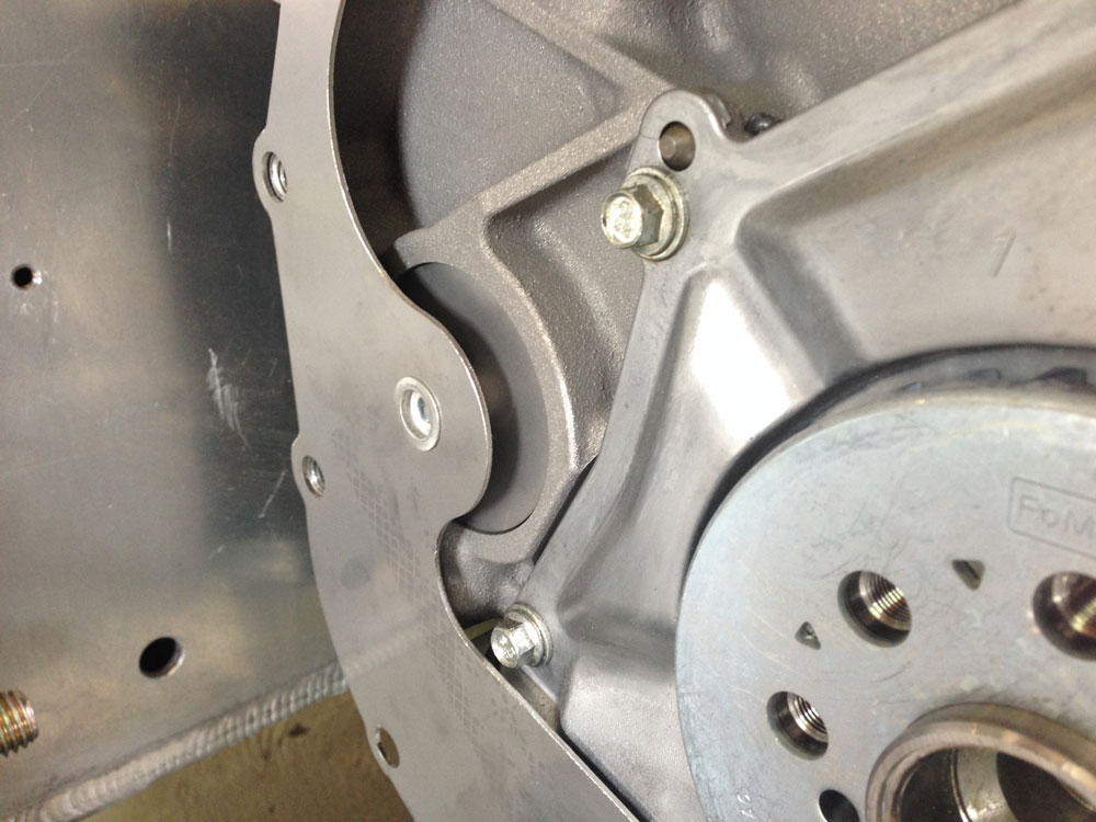
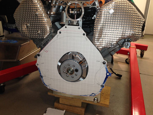
At the top of the block plate I extended the plate with two holes to assist in stabilising the throttle drive assembly. I have reversed my InnoV8 8-stack to clear the high mount alternator so this modification was required.
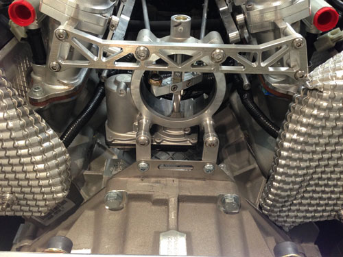
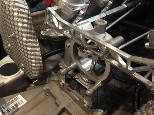
All in all it was a great outcome. All holes lined up perfectly and I have 2 spare ones as well in case I ever need any more!
Update : 28th October, 2013
Engine Water Cooling Cross Over Tube & Wiring
Work to fit the Coyote engine water cooling cross over plumbing was started. A custom alloy water port was machined up, a T-fitting installed and a water hose made to get around the top mount alternator.
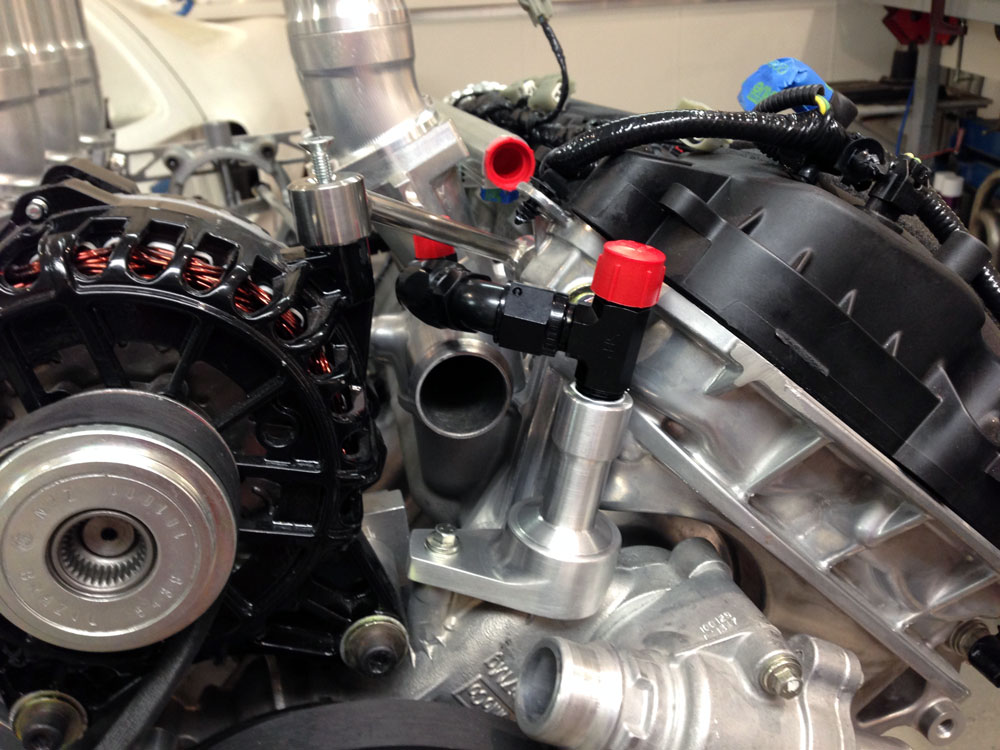
The top of the T-fitting will go to the overflow tank.
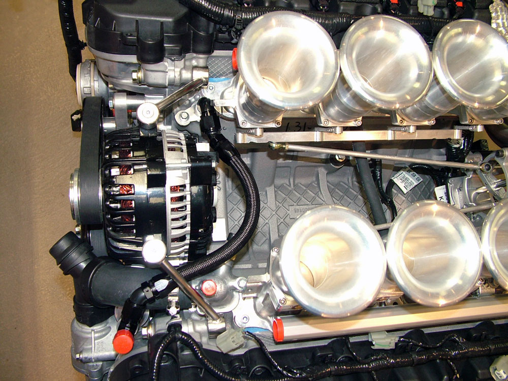
Next job was to optimise the engine harness layout. With the eight stack the harness fitted poorly and looked terrible on top of the engine. The goal was to move a lot of the harness into the V of the engine between the eight stack. First job was to make an attachment point for the harness between the inlet. The harness was completely stripped down. An alloy rod was attached to the fuel rail towers and corresponding harness clips added in the appropriate positions. Heat reflective tape was used for areas close to the extractors.
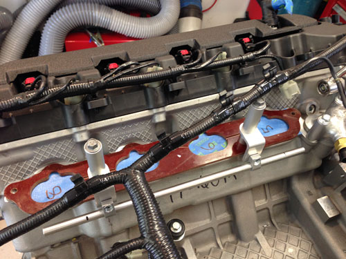
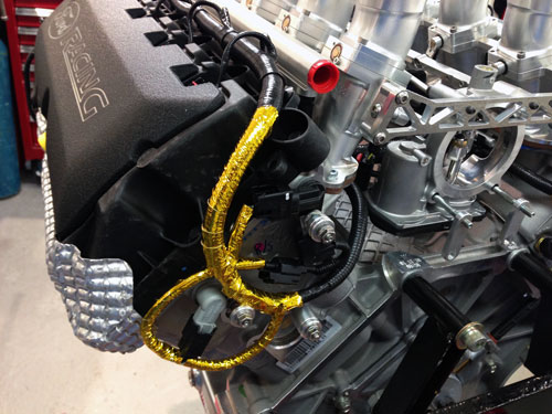
The new position for the harness cross over in the Valley and an extension for the fly by wire connector added. This modification tool a loot of cable away from the injector and coil wires on the top of the engine.
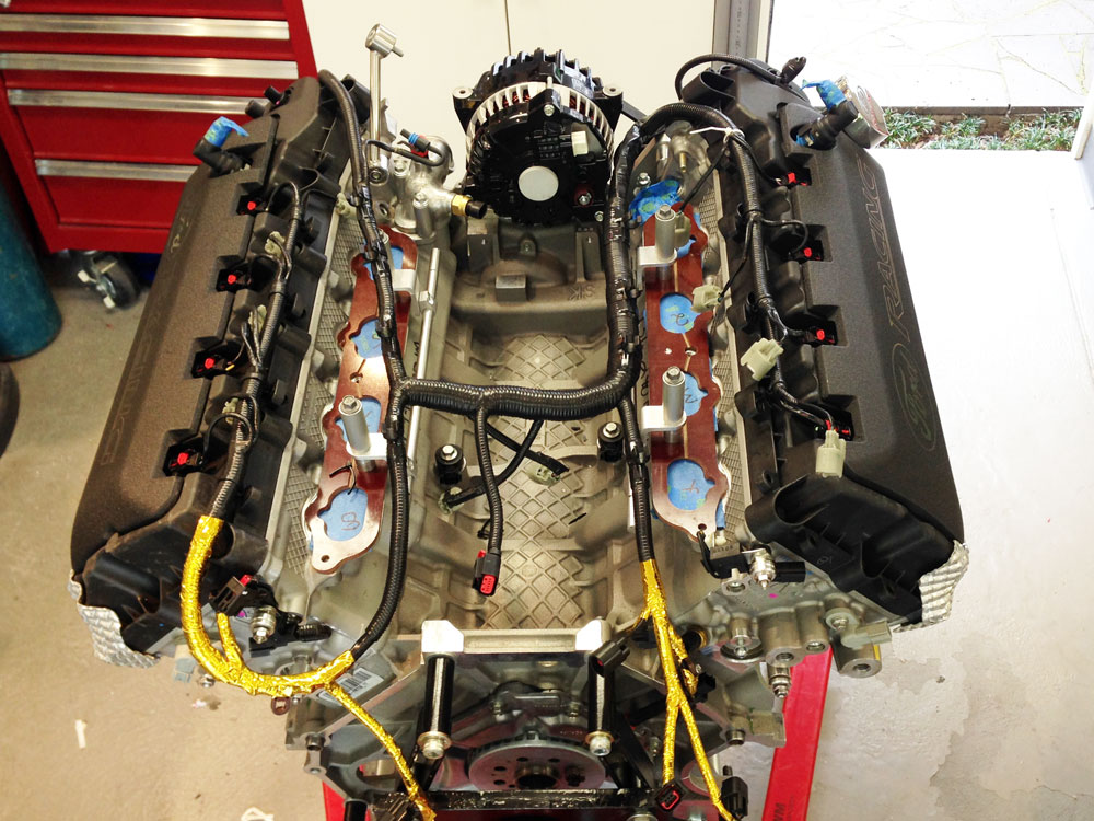
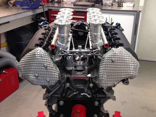
This modification hides as much cable as possible from the top of the engine. Lastly custom heat shields were made to protect the cable and cam sensors from the radiant heat that will be generated by the extractors.
Update : 7th October, 2013
Exhaust
Continued work has seen the whole exhaust system to the outlets tacked together. I tell you this can be fiddly work and take a lot of time to get things right. Having everything straight and level and matched left to right is hard. The Burns stainless racing mufflers are very nice and very light. With simple 3" outlets it looks very understated from the rear of the car.
I'm not sure how effective these race mufflers from Burns Stainless will be but time will tell.
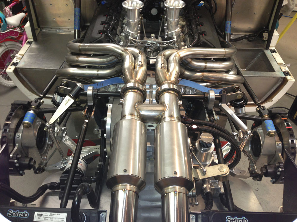
I will also be getting the system ceramic coated on the inside, I want to leave the outside in stainless.
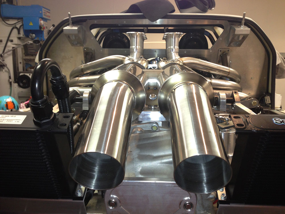
Getting enough downward angle to get the outlet to exit the rear clip at a visually acceptable angle was VERY difficult because of the huge Ricardo transaxle. I had to be very creative where the transaxle selector shaft is located!
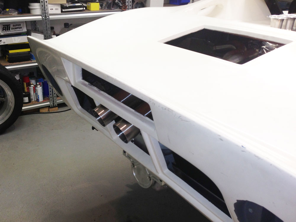
All in all it looks OK. So now to get the exhaust fully welded while gas purging the system.
Update : 7th July, 2013
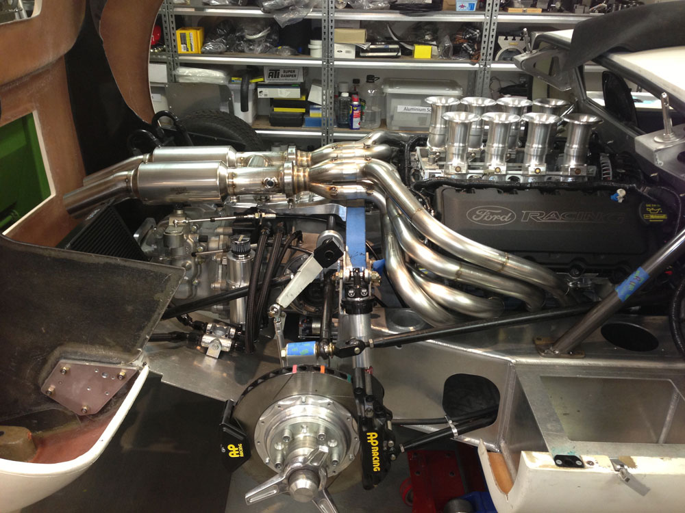
Extractors
Work to develop an extractor system for performance first has been undertaken recently. Moving to a non cross-over system to have the right primary length was a priority as well as a H-pipe and the right primary diameter. Design was developed using an exhaust simulation program to determine primary size and length. Roaring Forties in Australia fabricated the first side below to meet the requirements. Four different bend radius tube configurations were used to create a design that looked fairy "organic" and allowed the system to fit in a car with little room due to the large Coyote engine and huge Ricardo transaxle. Equal length is achieved as far as practical. Work to finish the other side and the custom race mufflers will continue soon.
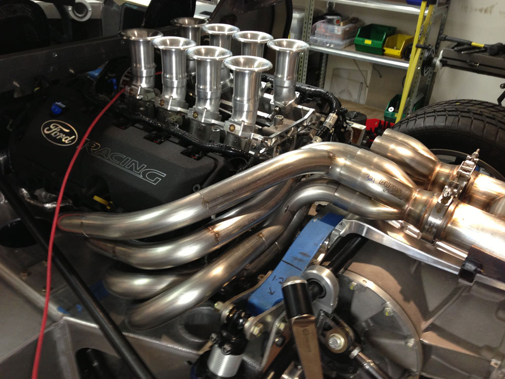
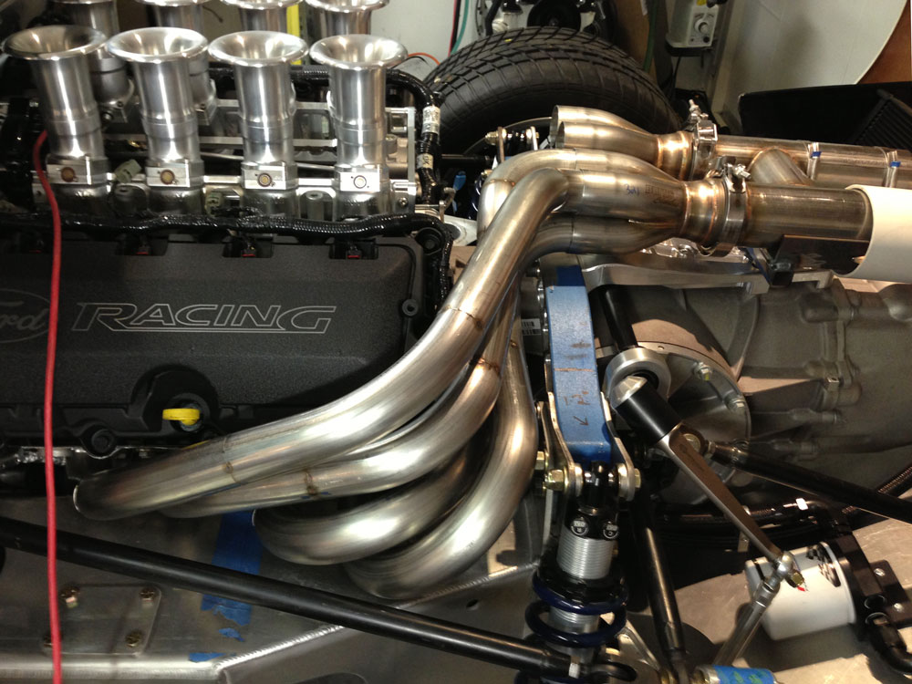
All tubing is stainless steel and it will be double ceramic coated on the inside to control the temperature in the engine bay.
Update : 3rd June, 2013
Transaxle and Engine Coolers
I decided to fit air to oil coolers, I was looking at a Laminova water to oil cooler but was worried about routing hoses to the front of the engine. I decided to fit air to oil coolers at the rear for mostly visual reasons. I wanted to see radiators through the back of the car! I do not plan on fitting any alloy covers on the rear clip. Brackets were made out of 2.5mm aluminium to mount the coolers.
I also decided to go with the same size coolers one of which is oversized for the transaxle. This was only done for symmetry when looking at the rear of the car. A pretty bad reason but what the hell!
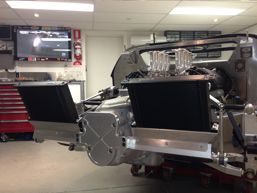
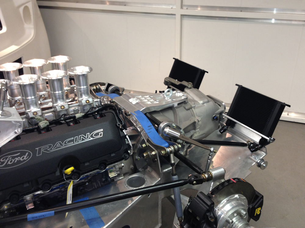
I have a Mocal thermostat for the transaxle (thanks for the tip Fran) which will help warm up the oil so that side is fine. I also have a thermostat for the engine side. Transaxle lines are AN-10 and engine in AN-12.
Update : 6th February, 2013
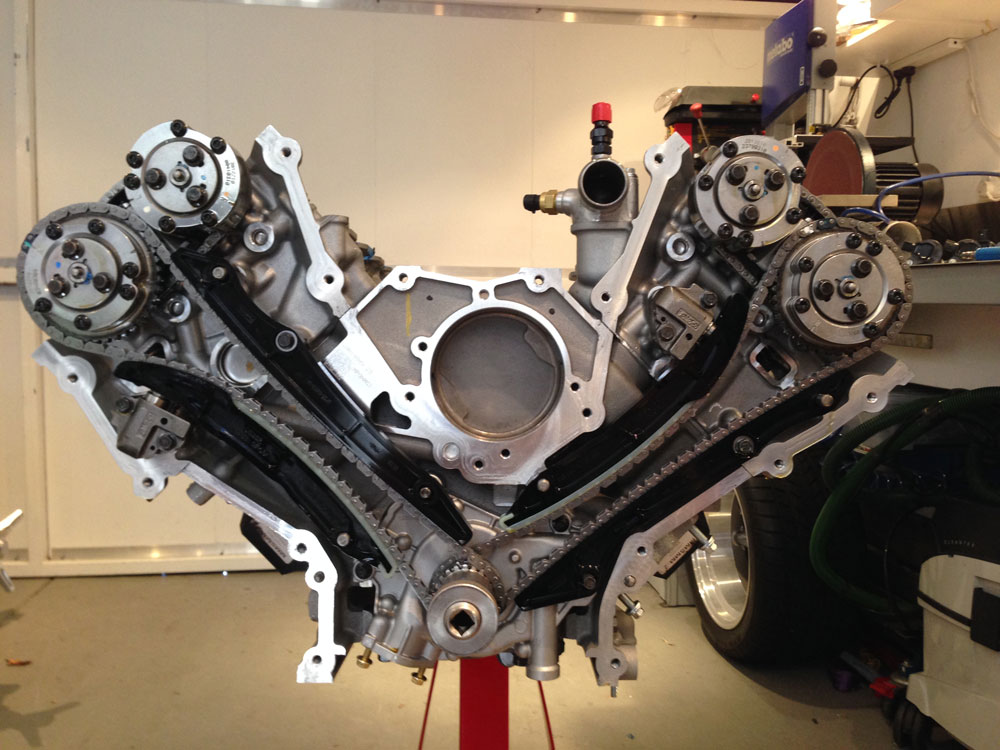
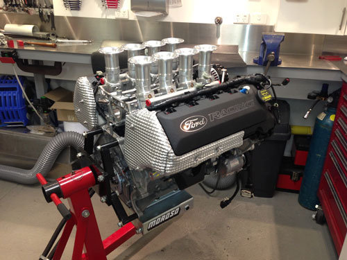
Coyote Engine
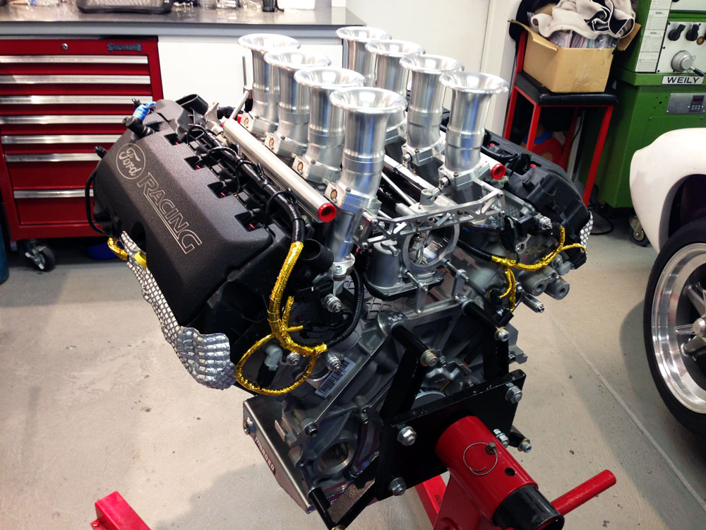
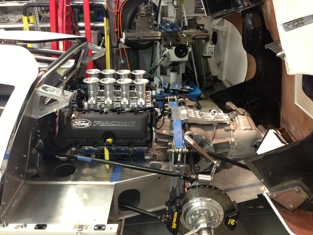
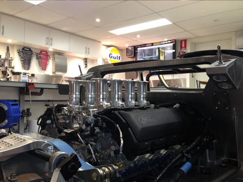
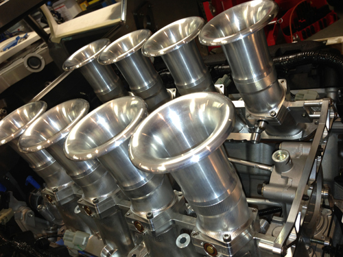
Well finally I have the engine I want in the GT40. Yep its a soon to be further upgraded Coyote aluminator motor. As you can see it has a billet alloy 8 stack inlet which is a work of art supplied by Roaring Forties in Melbourne Australia. Full drive by wire system, Australian designed and manufactured especially for the GT40. Very happy with it.
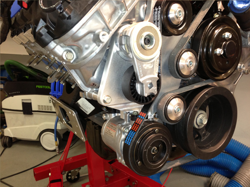
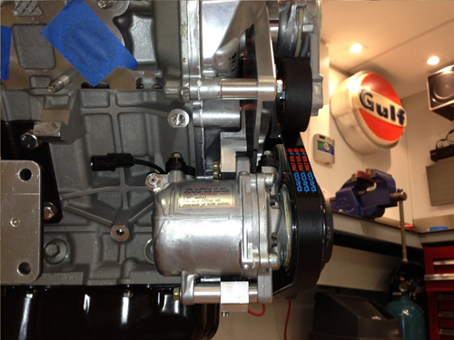
I designed and manufactured a full custom serpentine layout to fit the ford alternator in the engine valley and a small but capable AC compressor in the tight engine bay without cutting into the RCR chassis. Big job as I had never built one before. Thanks to Roaring Forties for some guidance in this area especially with the alternator placement suggestion. pulley gauge lines are spot on and getting the right length belt only took three goes to get it perfect!
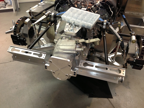
So how do take the rather large Coyote motor and the huge Ricardo and squeeze it into an RCR? You get a big saw out and start cutting! Well not quite! I had heard that the Coyote engine and Ricardo transaxle would not fit and that was correct, if things were not altered. To get the job done some suspension points were altered and the fire wall modified and it squeezed in pretty well. A check on the suspension changes was ana lysed locally in Australia to ensure that I was not killing the handling (thanks again Roaring Forties). I was later told by Fran of the mods that could be made to the car to fit, probably could have asked first, but it would have made it less of an adventure! I went down the same/similar route he has before, possibly not with a Ricardo, I'm not sure. Any others out there with a Coyote in an RCR give me a yell, it would be good to discuss any challenges you are having.
Test headers were fitted to make sure the exhaust could exit with the chassis of the RCR. Its again tight but do-able.
I also made custom engine mounts (rigid). and the engine sits very far forward in the car and very low. There are many restrictions imposed by the Ricardo as well as the Coyote but it all worked out OK. Took too long though! By deleting the adaptor plate some room was saved (a whole 1"!) and a Ford GT Supercar flywheel was also purchased which will bolt to the engine and mate perfectly (I hope!) to the transaxle.
Engine mods are next, have a oil pan that fits and internal engine parts on the way to make sure I can get a "bit" more power out of the thing.
Update : 31th January, 2013
CRFM
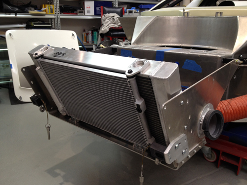
I decided to over cool my engine and design a larger radiator than the stock RCR unit. There is nothing wrong at all with the RCR unit, I just really wanted to fill the available under bonnet area. I will also be using a large AC condenser so I wanted to account for the impact on the radiator. I designed the following unit for manufacture:
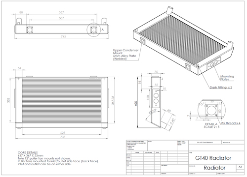
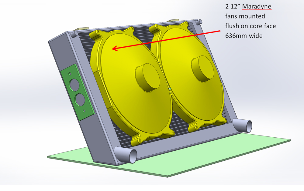
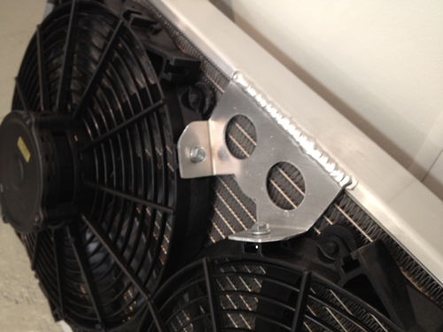
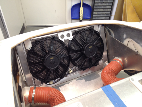
Core face area is much larger. I also wanted to accommodate higher power 12"fan units (each delivers 1565 CFM at 0" static). These large 318mm diameter fans will cover the maximum core face.
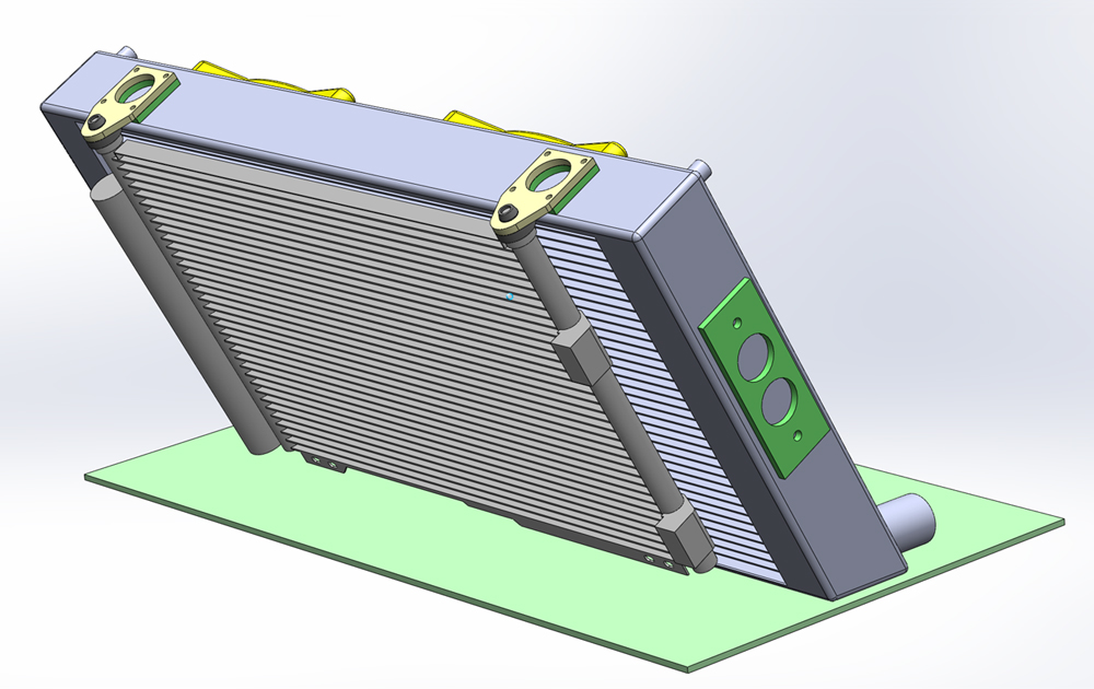
The resulting radiator is quite a size jump over the standard unit as can be seen below.
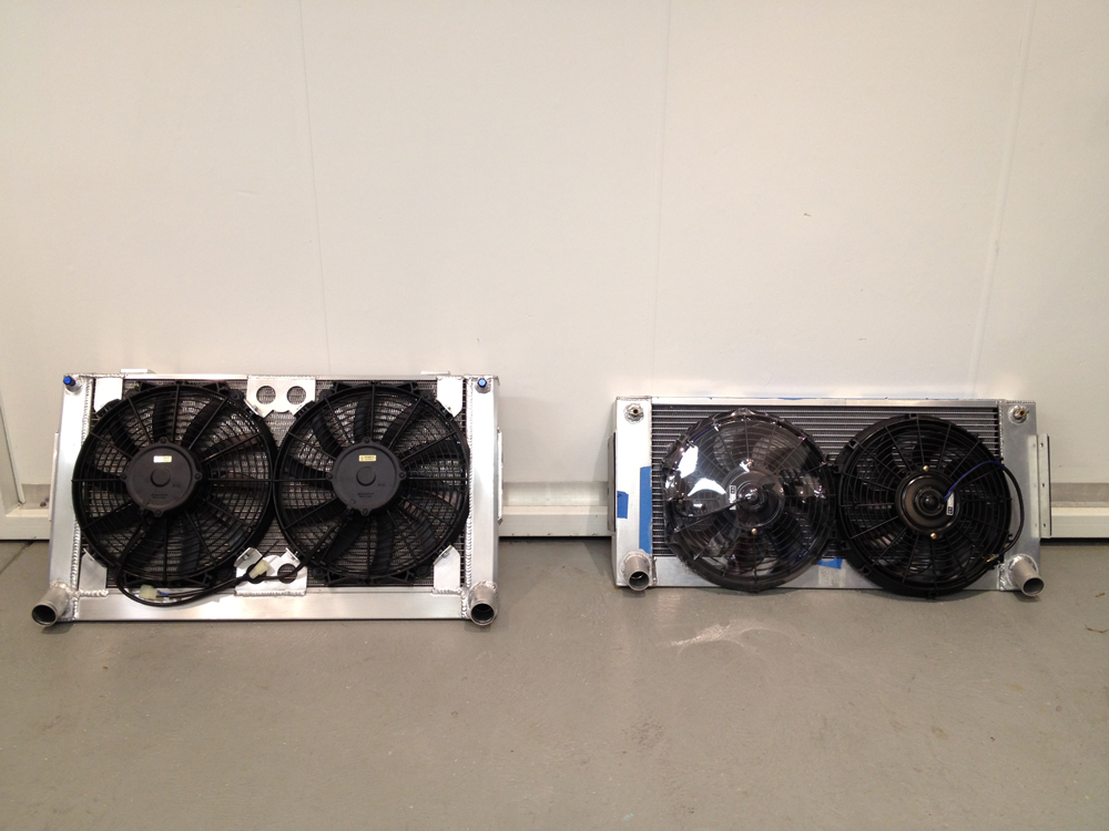
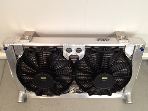
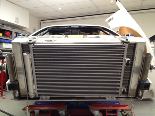
It also fills the entire frontal area available compared to the stock unit.
I am very happy with the result but it was a lot of work!
Update : 10th May, 2012
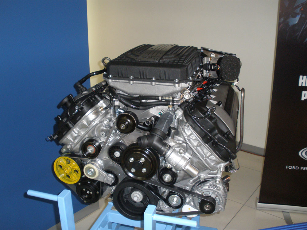
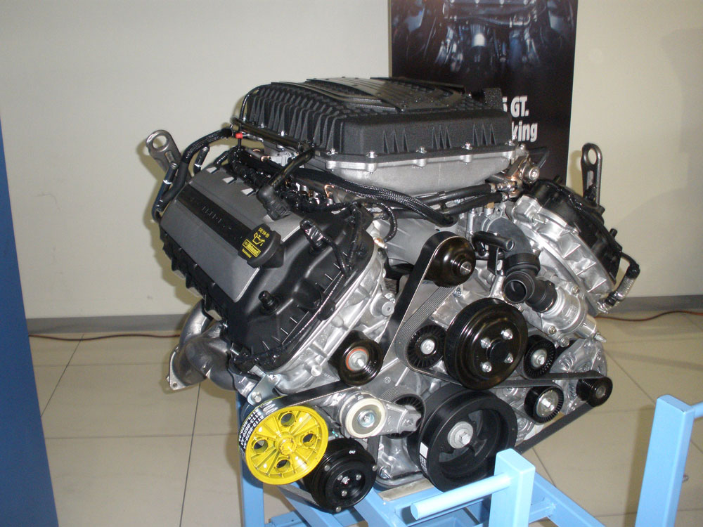
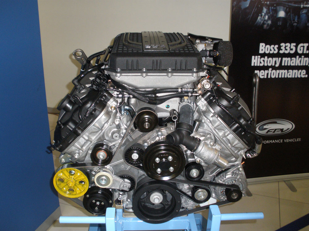
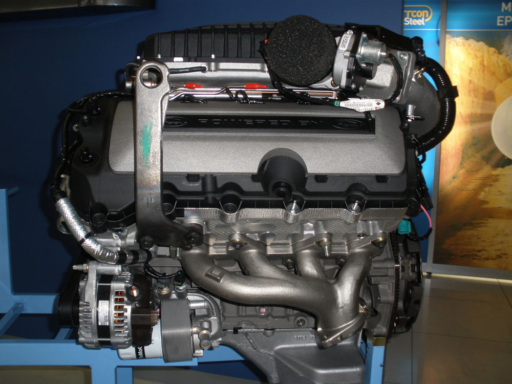
Ford Coyote Engine
Images below are the supercharged Ford Coyote engine. Possibly an option but hard to get. Still pretty big too.
Update : 28th October, 2010